Heckler&Koch MR762A1-LRP User Manual
Page 15
28
29
REASSEMBLY (ASSEMBLY) OF THE MR762A1
Tools Needed: MR762A1 Disassembly Tool (located in the Buttstock), 5mm Allen Wrench,
Small Straight Slot Screwdriver
1. Lower Receiver:
a. Check to ensure that the buttstock tightening screw is loose before attempting
to install the buttstock. If tight, insert the large tip (3mm hex) of the MR762A1
Disassembly Tool into the tightening screw and rotate (but do not completely remove)
counter clockwise.
b. Two small set screws are located on the bottom of the receiver extension (buffer
tube). These set screws are provided to eliminate any play that may develop
between the buttstock and the extension. The left hand side of the set screw
features a detent surface that engages the buttstock. The right hand surface
features a cut to accommodate a small straight slot screwdriver. Rotating the set
screws clockwise will tighten the detents to the buttstock; rotating the setscrew
counter clockwise will loosen the buttstock. Using a straight slot screwdriver, rotate
the set screws clockwise using quarter turns and adjust until the detents engage the
buttstock but do not hinder removal or installation (Fig. 37)
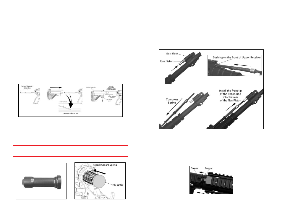
Fig. 37 – Buttstock reassembly
c. Depress the back of the buttstock release lever allowing the front tab to pivot
downwards. Pull down on the front tab until the locking pin is not visible inside
the buttstock. Mount the buttstock onto the receiver extension. The buttstock is
adjustable for length of pull, with five different settings available to the operator.
WARNING: Ensure that only the proprietary HK buffer and recoil spring (action
spring) are installed in the MR762A1. Use of non HK buffers and recoil springs could
result in cycling problems and affect the reliability of the MR762A1 (Fig. 38).
Fig. 38 – HK MR762A1 Proprietary Buffer Fig. 39 – Installing buffer & action spring
d. Ensure that the hammer is in the down (cocked) position before attempting to install
the buffer and action spring. Mount the action spring onto the buffer and insert the
buffer and spring into the receiver extension. Push back on the buffer far enough
until the buffer is retained by the spring loaded buffer detent (Fig. 39).
2. Upper Receiver:
a. Install the gas piston into the back of the gas block. The piston rings need not be
staggered prior to installation (Fig. 40).
Fig. 40 – Reinstalling the Gas Piston and the Piston Rod
b. Insert the rear of the piston rod into the bushing located at the front of the upper
receiver above the barrel nut, compress the spring, and install the front tip of the
piston rod into the rear of the gas piston.
c. Slide the Free Floating Rail System (FFRS-handguard) onto the barrel nut, ensuring
that the tongue on the FFRS mounts into the groove on top of the upper receiver.
Once the FFRS is flush with the upper receiver, drift in the captive FFRS retaining
screw. Insert a 5mm hex wrench into the retaining screws and rotate clockwise until
hand tight.
Fig. 41 – Reinstalling the FFRS handguard