Heckler&Koch MR762A1-LRP User Manual
Page 7
12
13
SECTION 3 — FUNCTION AND OPERATION
The function and operation of the MR762A1 is similar to that found in semi-automatic
firearms and consists of eights steps: (1) Feeding, (2) Chambering, (3) Locking, (4) Firing,
(5) Unlocking, (6) Extracting, (7) Ejecting, and (8) Cocking.
These eight steps are explained below with a brief description of what occurs inside the
rifle during each step. Assume that a full magazine is loaded in the rifle with the magazine
follower spring forcing the follower and thus the top cartridge into the path of the bolt and
the bolt is locked to the rear.
(1) Feeding. The bolt is released from the bolt catch, either by deploying and then
releasing the charging handle or by depressing the bolt catch. The bolt assembly moves
forward, being driven by the expansion of the recoil spring. The bottom locking lugs on
the bolt head act as a feed pawl, striking the top cartridge off the magazine and moving
the cartridge towards the chamber in the rear of the barrel.
(2) Chambering. The recoil spring continues to drive the bolt assembly forward until the
bolt head seats the cartridge into the barrel’s chamber. Chambering is complete when the
extractor snaps into the extracting groove on the cartridge and the ejector is forced into
the face of the bolt.
(3) Locking. Locking occurs when the bolt reaches its limit of forward travel. When the
bolt is moving forward, the cam pin orients the bolt head by ensuring that the locking
lugs on the bolt head will pass between the gaps of the locking lugs located on the barrel
extension (chamber). The bolt then strikes the back of the barrel and then stops. The
action spring continues to move the bolt head carrier forward, thus causing the cam pin
to pivot on the bolt head’s raceway. This action pivots the bolt head and rotates the bolt
head’s locking lugs counter-clockwise until they engage the locking lugs on the barrel
extension. The bolt assembly is now locked into the upper receiver.
(4) Firing. Firing occurs when the firing pin strikes the primer in the head of the cartridge.
When the trigger is pulled, the trigger’s sear surface disengages from the hammer’s
intercept notch and the hammer releases. The hammer moves forward under pressure
from the hammer spring, disengaging the drop safety, striking the firing pin, and
overcoming the inertia of the firing pin spring. This drives the firing pin against the primer,
which in turn ignites the propellant in the cartridge case and propels the bullet through the
barrel.
(5) Unlocking. Unlocking occurs after a cartridge is fired. As the bullet is forced through
the barrel by expanding gases, a small amount of gas enters through the gas port into the
gas block. The gas block features a small expansion chamber that quickly fills up with gas.
The gas then hits the front of the gas piston, causing the three piston rings to expand, and
driving the gas piston rearwards. Because the pusher rod is mounted in the gas piston, the
pusher rod moves back as well. The back of the pusher rod hits the anvil (string surface)
on top of the bolt head carrier, causing the bolt head carrier to move rearwards. As the
bolt carrier assembly moves rearward, the bolt cam pin rotates and unlocks the bolt from
the locking lug recesses in the barrel extension. The unlocked bolt is now ready to move
rearward. Any remaining gas follows the bullet out of the muzzle.
(6) Extracting. Extracting removes the empty cartridge case from the chamber. As the
bolt unlocks, the bolt rotates slightly counterclockwise, causing the extractor to rotate the
cartridge case within the chamber. The expanded case breaks contact with the chamber
walls, allowing extraction to occur.
(7) Ejecting. Ejecting throws the empty cartridge case out of the receiver. As soon as the
bolt has drawn the cartridge case clear of the chamber, the force of the ejector spring and
plunger pushes the cartridge case head away from the bolt face. This causes the forward
end of the cartridge case to move outward to the right. A deflector on the outside of the
upper receiver deflects the cartridge case away from operator.
(8) Cocking. Cocking occurs when the hammer is forced into position for firing the next
cartridge. This happens as the bolt carrier assembly travels toward the rear. The bolt
carrier assembly forces the hammer back and rides over it. The hammer is caught by the
disconnector if the trigger is still held to the rear and by the trigger’s sear surface if the
trigger has been released.
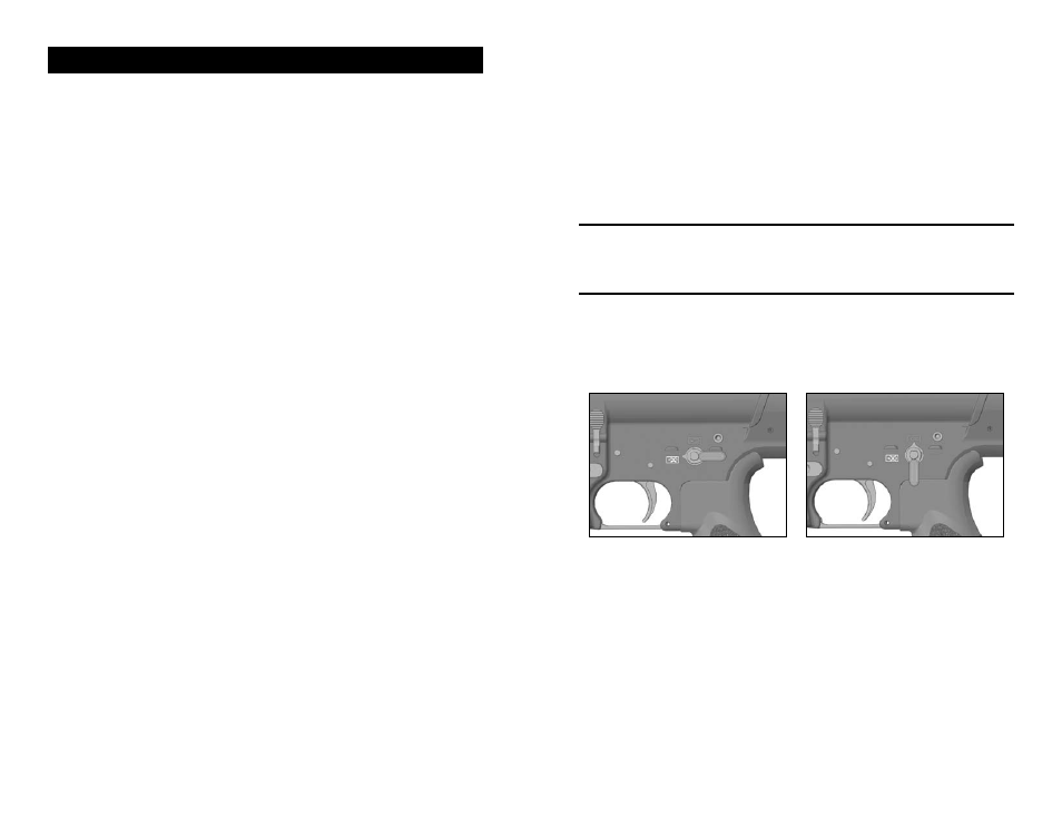
SELECTOR/SAFETY LEvER FUNCTION
NOTE: The MR762A1 has ambidextrous selector/safety levers, that is safety levers
located on both sides of the lower receiver. Either lever can be manipulated and
moves the lever on the other side. Unlike many AR-style firearms, the selector/safety
levers of the MR762A1 can be placed on the “SAFE” position even if the MR762A1
is not cocked.
“SAFE POSITION” – Place the selector lever with the point facing towards the closed
white box containing a bullet symbol with an “X” over it (towards the muzzle, Fig. 3).
“SEMI-AUTOMATIC POSITION”– Place the selector lever with the point towards the
closed red box containing a red bullet symbol in it (straight up position) (Fig. 4).
Fig. 3 – SAFE Fig. 4 – SEMI-AUTO