Heckler&Koch MR762A1-LRP User Manual
Page 12
22
23
SECTION 7 — DISASSEMBLY & ASSEMBLY
DISASSEMBLY (FIELD STRIPPING) OF THE MR762A1
Tools Needed: MR762A1 Disassembly Tool (located in the Buttstock), 5mm Allen Wrench
1. Clear the MR762A1
a. Point the muzzle in a safe direction with the finger off the trigger and outside the
trigger guard.
b. Place the selector lever on “SAFE”
NOTE: The MR762A1 has ambidextrous selector lever/safety levers, that is safety
levers located on both sides of the lower receiver. Either lever can be manipulated
and moves the lever on the other side. Unlike many AR-style firearms, the selector
lever/safety levers of the MR762A1 can be placed on the “SAFE” position even if the
MR762A1 is not cocked.
c. Remove the magazine (if applicable) by depressing the magazine release button
located on the right hand side of the lower receiver.
d. Depress the catch located on the charging handle and rack the bolt to the rear two
or three times in quick succession to extract and eject any cartridges that may have
been loaded into the barrel.
e. Lock the bolt to the rear by pulling the charging handle all the way back. Once the
bolt reaches its limit of rearward travel, depress the bottom of the bolt catch located
on the left hand side of the lower receiver.
f. Perform a visual inspection of the chamber area to ensure that no live rounds are
present in the MR762A1 prior to disassembly.
g. Return the bolt to battery (all the way forward) by either depressing the grooved
paddle (top portion) of the bolt catch or by slightly pulling back on the charging
handle until the bolt catch disengages from the bolt and then allow the action spring
to move the bolt forward.
CAUTION: Never attempt to disassemble the MR762A1 with the bolt locked back to
rear. After performing the clearance procedure, always ensure the bolt is forward
before attempting to disassemble.
2. Separating the Upper and Lower Receivers:
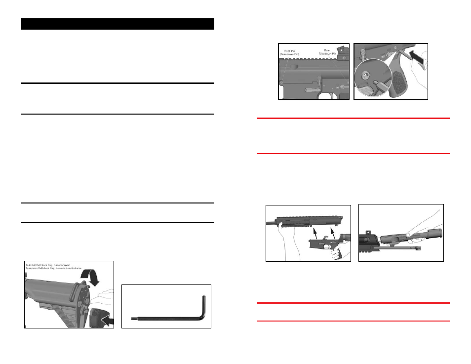
a. Rotate the recoil pad counter clockwise one quarter turn and separate the recoil pad
from the buttstock. Remove the MR762A1 disassembly tool (Fig. 20, 21). This pertains
to standard model MR762A1 ONLY, not the MR762A1 LRP model. LRP model normally
has the disassembly tool stored in the pistol grip.
Fig. 20 – Removing the disassembly tool Fig. 21 – Disassembly tool
b. Insert the small tip of the disassembly tool into the spring loaded detent located in
the center of the rear takedown pin. Push the disassembly tool from left to right until
the takedown pin reaches its limit of lateral travel (Fig. 22, 23).
Fig. 22 – Takedown Pins Fig. 23 – Takedown Pin Detail
WARNING: Always use the disassembly tool to disengage the detents on both the
rear takedown pin and the front pivot pin. Attempting to remove the pins without
disengaging the detents could lead to damaging the lower receiver. Both the rear
takedown pin and the front pivot pin are captive pins and will therefore remain
attached to the lower receiver. Attempting to completely remove the takedown and
pivot pins could lead to damaging the lower receiver.
3. Bolt Assembly:
a. Remove the upper receiver from the lower receiver (Fig. 24A), depress the catch
on the charging handle and withdraw the bolt assembly from the rear (Fig. 24B).
Continue to pull the charging handle to the rear until resistance is encountered.
Lift up on the charging handle and separate the charging handle from the upper
receiver.
Fig. 24A – Removing the upper receiver Fig. 24B – Removing Bolt & Charging Handle
b. Insert the small tip of the disassembly tool into the right hand side of the firing pin
retaining pin and drift the firing pin retaining pin from right to left until the firing pin
retaining pin reaches its limit of lateral travel (Fig. 25).
WARNING: The firing pin retaining pin is a captive pin and will therefore remain
attached to the bolt carrier. Attempting to completely remove the firing pin retaining
pin could lead to damage of the bolt assembly.