Balance the model (c.g.), Set the control throws – Great Planes Venus II 60 ARF - GPMA1027 User Manual
Page 24
Use a Great Planes AccuThrow (or a ruler) to accurately
measure and set the control throw of each control surface as
indicated in the chart that follows. If your radio does not have
dual rates, use the low rate settings.
At this stage the model should be in ready-to-fly condition
with all of the systems in place including the engine, cowl,
propeller, spinner and all components of the radio system.
❏
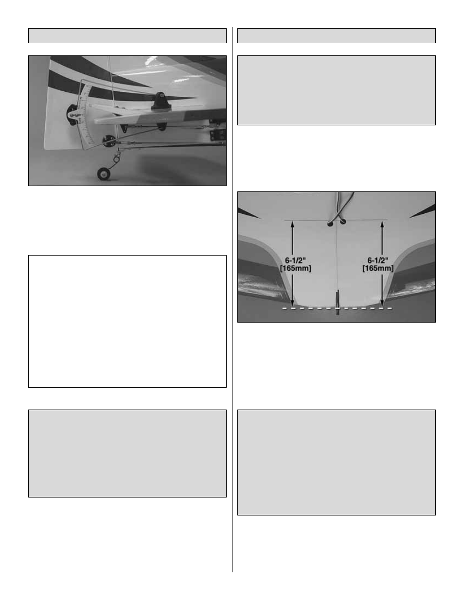
1. If you will be using a Great Planes C.G. Machine to
balance the model, mount the wing to the fuselage and
proceed to the next step. If you will not be using a C.G.
Machine, use a fine-point felt-tip pen to accurately mark the
C.G. on the top of the wing 6-1/2" [165 mm] back from the
flat part of leading edge at the middle. Lay a piece of narrow
(1/8" [2 mm]) tape over the line so you will be able to feel it
with your fingers when lifting the model to check the C.G.
❏
2. With the wing attached to the fuselage, all parts of the
model installed (ready to fly) and an empty fuel tank, place
the model upside-down on the CG Machine or lift it upside-
down at the balance point you marked.
This is where your model should balance for the first flights.
Later, you may wish to experiment by shifting the C.G. up to
1/2" [13 mm] forward or 1/2" [13 mm] back to change the
flying characteristics. Moving the C.G. forward may improve
the smoothness and stability, but the model will then be less
aerobatic and may require more speed for takeoff and
make it more difficult to slow for landing. Moving the C.G. aft
makes the model more maneuverable, but could also cause
it to become too difficult to control. In any case, start at the
recommended balance point and do not at any time
balance the model outside the specified range.
More than any other factor, the C.G. (balance point) can
have the greatest effect on how a model flies, and may
determine whether or not your first flight will be
successful. If you value this model and wish to enjoy it for
many flights, DO NOT OVERLOOK THIS IMPORTANT
PROCEDURE. A model that is not properly balanced will
be unstable and possibly unflyable.
Balance the Model (C.G.)
IMPORTANT: The Venus II ARF has been extensively
flown and tested to arrive at the throws at which it flies
best. Flying your model at these throws will provide you
with the greatest chance for successful first flights. If, after
you have become accustomed to the way the Venus II
ARF flies, you would like to change the throws to suit your
taste, that is fine. However, too much control throw could
make the model difficult to control, so remember, “more is
not always better.”
These are the recommended control surface throws:
High Rate
Low Rate
ELEVATOR:
9/16" [14 mm] up
3/8" [10 mm] up
9/16" [14 mm] down 3/8" [10 mm] down
RUDDER:
3" [76 mm] right
1-3/4" [44 mm] right
3" [76 mm] left
1-3/4" [44 mm] left
AILERONS:
7/8" [22 mm] up
1/2" [13 mm] up
7/8" [22 mm] down
1/2" [13 mm] down
NOTE: The throws are measured at the widest part of the
elevators, rudder and ailerons.
Set the Control Throws
24