Mount the servos and hook up the controls – Great Planes Venus II 60 ARF - GPMA1027 User Manual
Page 17
EXTERNALLY MOUNTED SERVOS
❏
1. Connect 24" [610 mm] servo extensions to the rudder
servo and both elevator servos. Secure the connections with
the heat shrink tubing provided with this kit.
❏
2. Guide the servo wires through the fuselage up into the
radio compartment and mount the servos using the screws
that came with them (the holes should have been previously
drilled and hardened).
❏
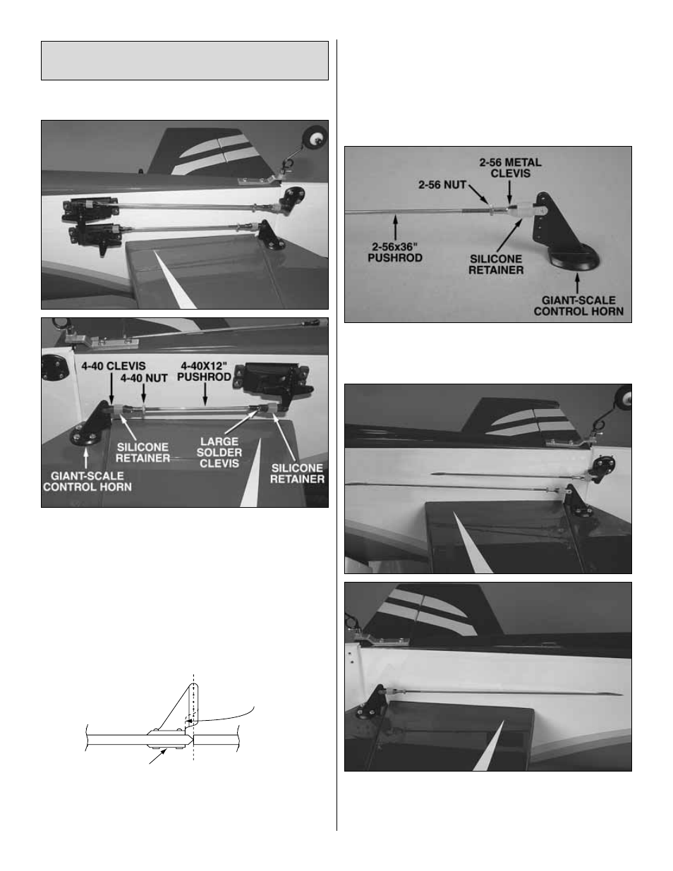
3. Make the pushrods and connect the servos to the
control surfaces using the hardware shown in the photos.
When mounting the horns, locate the pushrod holes over the
pivot point and use 4-40 x 5/8" [16 mm] Phillips screws and
the mounting plates to mount the horns. Drill 1/8" [3.2 mm]
holes through the rodder for the screws. Note: Trim the
rudder horn as shown so it will not interfere with the fuselage.
INTERNALLY MOUNTED SERVOS
❏
1. Make three identical pushrod assemblies like the one
shown in the photo. (Turn the clevises approximately fifteen
full turns onto the pushrods.)
❏
2. Guide the pushrods through the guide tubes in the
back of the fuselage and mount the horns with 4-40 x 5/8"
[16 mm] Phillips screws and the back plates on the other
side. Use a 1/8" [3.2 mm] drill for the screws.
ALIGN THE PU
S
HROD
HOLE
S
WITH THE PIVOT
TRIM HERE
(FOR RUDDER ONLY)
MOUNTING PLATE
Mount the Servos and
Hook Up the Controls
17