Great Planes Venus II 60 ARF - GPMA1027 User Manual
Page 16
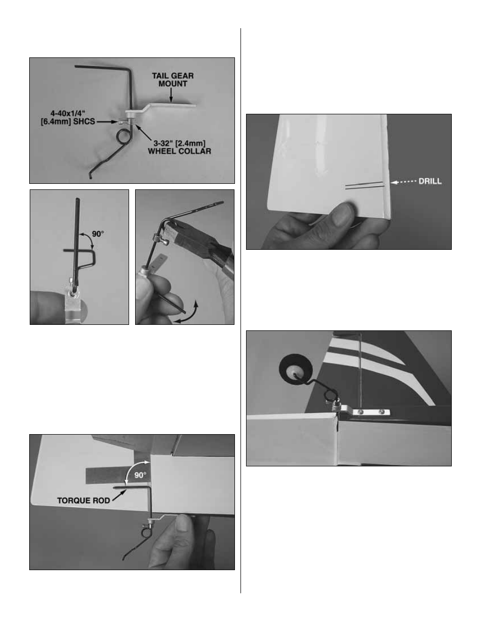
Before joining the rudder to the fin, the tail gear has to
be put together…
❏
15. Slide a 3/32" [2.4 mm] wheel collar onto the tail gear
wire and tighten it down with a drop of threadlocker and a
4-40 x 1/4" [6.4 mm] SHCS (socket-head cap screw). Install
the tail gear mount as shown, and then use pliers to bend the
wire. Viewed from above, the bend should be 90-degrees to
the axle part of the wire where the wheel goes. If the bend
has to be adjusted, hold the wire with pliers at the coil and
bend the wire as necessary to achieve the 90-degree angle.
Refer to this photo for the next two steps.
❏
16. Temporarily join the rudder to the fin and fuselage
with three hinges. Lay the tail gear wire on the fuselage as
shown. Make sure the “torque rod” part of the wire is
perpendicular to the leading edge of the rudder. Bend the
wire as necessary.
❏
17. Use a fine-point felt-tip pen to mark the rudder on
both sides of the wire.
❏
18. Set the tail gear wire aside and take out the rudder.
Using the marks on the rudder for alignment, drill a 3/32"
[2.4 mm] hole into the rudder for the torque rod part of the
wire. Use a 3/32" [2.4 mm] brass tube sharpened on the end
or a hobby knife to cut a groove in the leading edge of the
rudder to accommodate the tail gear wire.
❏
19. Use epoxy to glue the tail gear wire into the rudder.
Then before the epoxy hardens, join the rudder to the fin and
fuselage with the hinges. Permanently glue in the hinges
with thin CA. Mount the tail gear bracket by drilling two
3/32" [2.4 mm] holes for two #4 x 3/8" [9.5 mm] screws.
Temporarily mount the bracket with the screws, remove the
screws and harden the holes with thin CA. After the holes
have hardened, mount the bracket.
16