Great Planes Venus II 60 ARF - GPMA1027 User Manual
Page 20
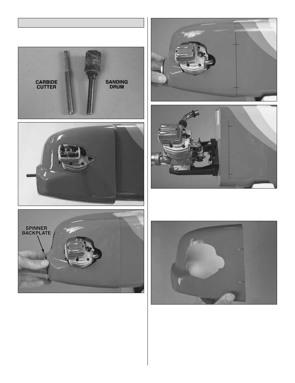
These are the cutting bits recommended
for cutting the holes in the cowl.
❏
1. Estimate the size, shape and location of the engine
cutout in the cowl. Use a fine-point felt-tip marker to draw a
rough shape of the cutout directly on the cowl. Use a carbide
cutter or similar high-speed rotary cutting tool to cut the
hole—start by making the hole small. Test fit the cowl to the
fuselage and enlarge the hole where necessary to get it to
fit. Use the backplate of the spinner to accurately position
the cowl so you will know where the cutout should be.
Hint: Until you have finalized the size and shape of the
engine cutout, it may be easier to remove and install the
cowl if the valve cover (for four-strokes) or engine head (for
two-strokes) is temporarily removed.
❏
2. With the cowl in position, use a fine-point felt-tip pen to
mark both sides of the aft edge of the cowl onto the
fuselage. Also mark four locations for the cowl mounting
screws on both the cowl and the fuselage. Remove the cowl.
❏
3. Using the lines on the sides of the fuselage as a
reference, drill 3/32" [2.4 mm] holes in the cowl at the four
marks so that the holes will be 3/16" [5 mm] aft of the
firewall—this will center the screws in the edges of the firewall.
❏
4. Reposition the cowl onto the fuselage and “center it
up” using the backplate of the spinner. Using tape or an
assistant to hold the cowl in position, drill 3/32" [2.4 mm]
holes through the holes you already drilled in the cowl into
the sides of the firewall.
Mount the Cowl
20