Balance the model (c.g.) set the control throws – Great Planes RC Universe FlatOuts ARF - GPMA1117 User Manual
Page 18
To simplify setup, the high-rate (3D) control throws for this
model are automatically set by the geometry of the included
hardware. We do recommend, however, that you perform a
quick check as described below to make sure the throws are
set up correctly.
Note: If your radio has the capability, low-rates will make it
easier to perform precision aerobatics. We recommend 40%
endpoints for all low-rate throws. If your radio does not have
low-rates, set up the plane using only the high-rate throws.
Additionally, you may want to use the exponential function to
soften the control response around center. This is largely a
matter of personal taste, but helps many pilots balance the
extreme throws needed for 3D flying with the need to make
small corrections when in normal flight.
We recommend setting up your airplane according to the
following table as a starting point. Use the Angle Templates
included with the plane to verify that you are in the ballpark.
However, setting up models of this type is largely a matter of
personal taste. We encourage you to tune the throws to your
taste as you get more familiar with the aircraft. Many expert
3D fliers choose to increase their high-rate travel by using
higher endpoints.
If you are not able to achieve these control throws, double-
check your pushrod hookup and make sure any control
surfaces in question are operating smoothly. If you have a
computer radio, also make sure your endpoint adjustments
are properly set.
At this stage the model should be in ready-to-fly condition
with all of the systems in place including the motor, the
propeller, the battery, and the radio system.
❏
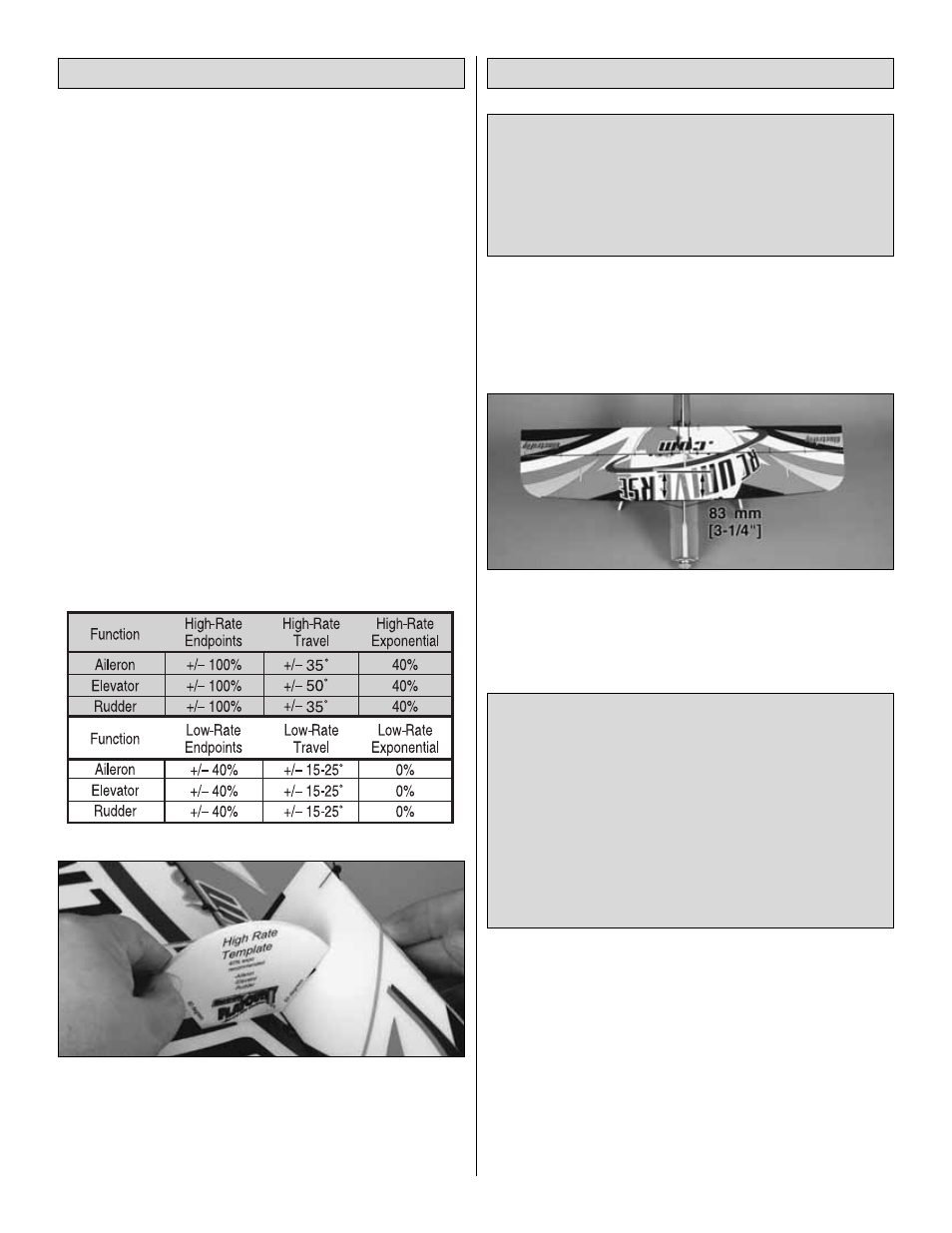
1. Use a felt-tip pen or 3 mm [1/8"]-wide tape to accurately
mark the C.G. on the underside of the top wing on both sides
of the fuselage. The C.G. is located 83 mm [3-1/4"] back from
the leading edge of the wing at the fuselage.
❏
2. With all parts of the model installed, including the
battery and propeller (ready to fly), lift it on your fingertips at
the balance point you marked.
❏
3. If the tail drops, the model is “tail heavy” and the
battery pack and/or receiver must be shifted forward or
weight must be added to the nose to balance. If the nose
drops, the model is “nose heavy” and the battery pack
and/or receiver must be shifted aft or weight must be added
to the tail to balance. If possible, relocate the battery pack on
the hook-and-loop strip to minimize or eliminate any
This is where your model should balance for the first
flights. Later, you may wish to experiment by shifting the
C.G. up to 13 mm [1/2"] forward or 13 mm [1/2"] back to
change the flying characteristics. Moving the C.G. forward
may improve the smoothness and stability, but the model
may then require more speed for takeoff and make it more
difficult to slow for landing or 3D aerobatics. Moving the
C.G. aft makes the model more maneuverable, but could
also cause it to become too difficult to control. In any case,
start at the recommended balance point. As with the
throws, though, we encourage you to experiment with the
CG until the model flies to your taste.
More than any other factor, the C.G. (balance point) can
have the greatest effect on how a model flies, and may
determine whether or not your first flight will be
successful. If you value this model and wish to enjoy it for
many flights, DO NOT OVERLOOK THIS IMPORTANT
PROCEDURE. A model that is not properly balanced will
be unstable and possibly unflyable.
Balance the Model (C.G.)
Set the Control Throws
18