Great Planes RC Universe FlatOuts ARF - GPMA1117 User Manual
Page 13
❏
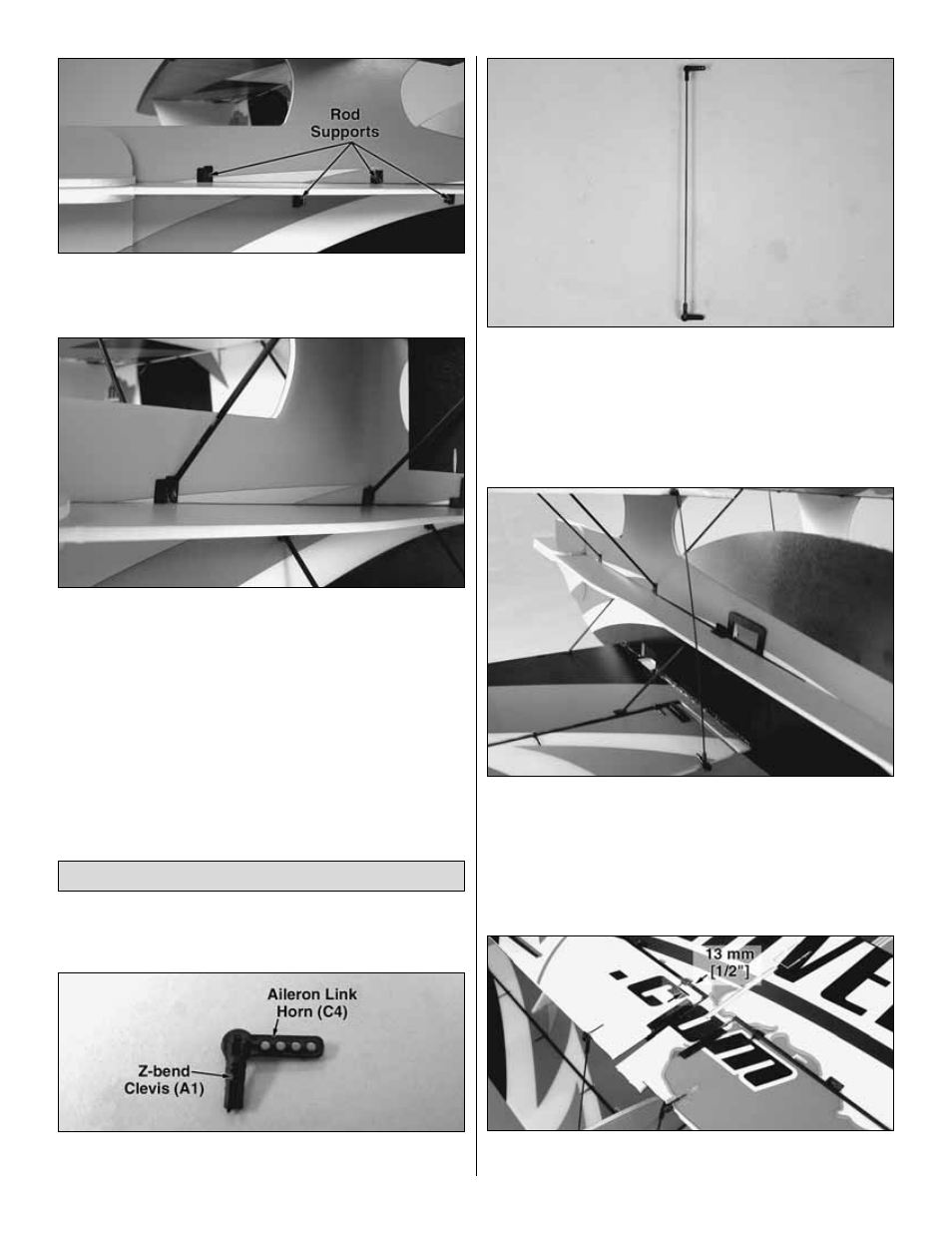
5. Correctly position the rod supports into the wings and
fuselage (test fitting the braces into the supports as needed)
and gluing them permanently when satisfied.
❏
6. Slide the braces into their respective rod supports
based on the completed picture above and center their
positions. Glue the braces one end at a time to the rod
supports. “Skew” the wing assembly if necessary during this
process so that all the rods evenly align and the top and
bottom wings are square to the fuselage.
❏
1. Locate four Z-bend clevises (A1) and four aileron link
horns (C4) and cut them from the parts tree.
❏
2. Press the clevises into the aileron link horns (C4) as
done in prior steps.
❏
3. Insert the two 1 x 165 mm [1/32" x 6-1/2"] aileron
joiner pushrods into the Z-bend clevises connecting the
top and bottom ailerons (sanding the ends of the pushrods
to a dull point will allow them to slide into the clevises
easier). Be sure that the Z-bend clevises are on the same
side of the link horns for each set of ailerons.
❏
4. Position the link horns into the slots at the trailing
edges of all four ailerons as shown and glue them into place.
Adjust the pushrods in the clevises so that the ailerons are
parallel. Add a couple drops of glue to each clevis at the
pushrod to secure them into place. Be careful not to glue the
clevises to the link horns.
❏
5. Glue four control surface braces (E1) onto the inside of
each aileron 13 mm [1/2"] back from the aileron leading edges.
Finish the Wings
13