Install the motor system – Great Planes RC Universe FlatOuts ARF - GPMA1117 User Manual
Page 16
❏
8. Insert two Z-bend clevises (A1) into the outer holes of a
double-sided servo arm that fits your servo and two Z-bend
clevises into the aileron control horns. Push the 1 x 80 mm [1/32"
x 3-1/8"] aileron pushrods into the clevises on the control
horns. Now attach the clevises in the servo arm onto the other
ends of the pushrods. Screw the arm onto the aileron servo and
adjust the depth of the pushrods in the clevises so that the
ailerons are in the neutral position when the servo arm is parallel
to the wing leading edge. When satisfied with their fit, a few
drops of glue on the pushrods will secure them in place.
❏
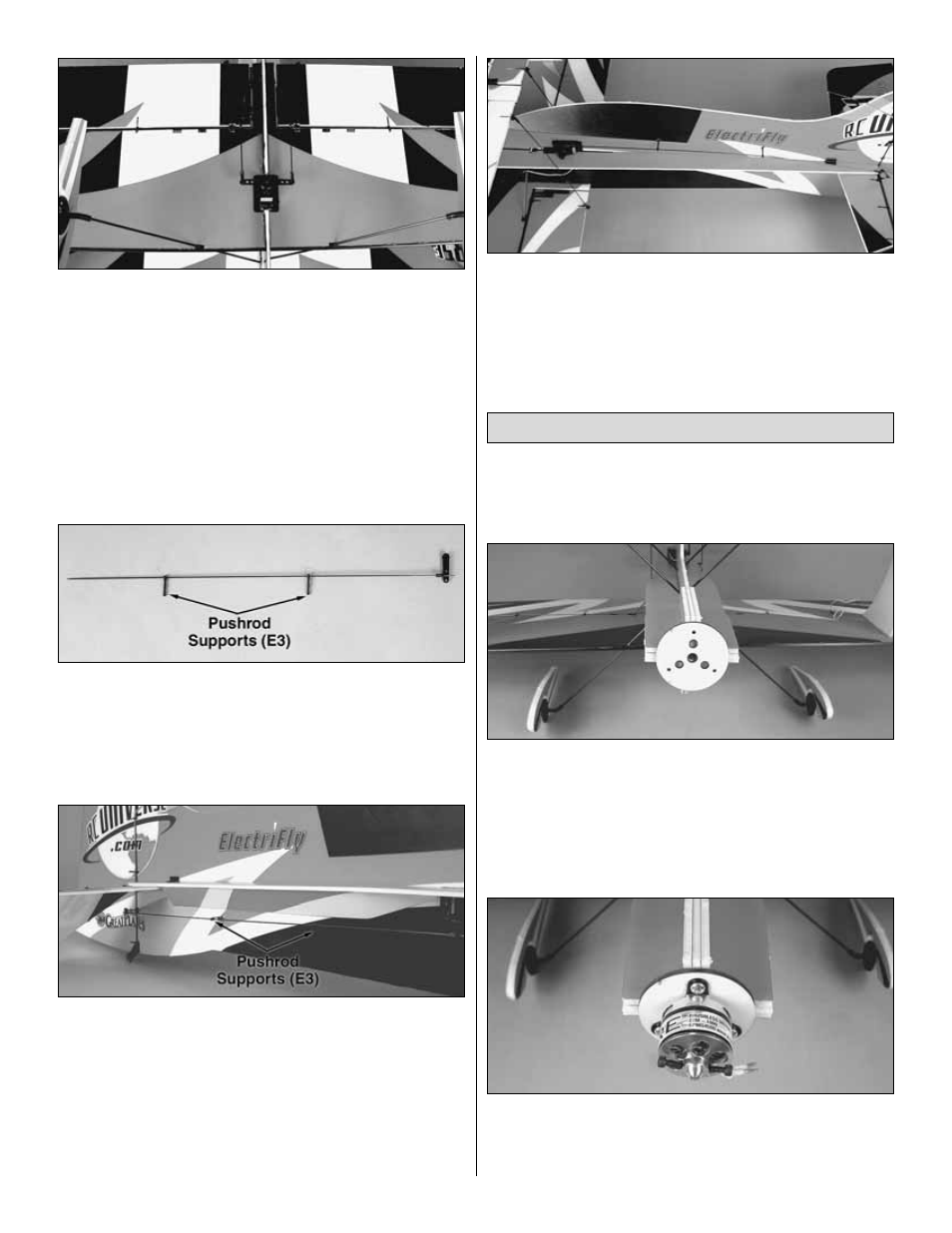
9. Fit a Z-bend clevis into the middle hole of a single-
sided servo arm that fits your servo. Slide the 1 x 340 mm
[1/32" x 13-1/2"] rudder pushrod into the clevis in the servo
arm and slide two pushrod supports (E3) onto the other
end of the rod.
❏
10. Attach the other end of the rudder pushrod to the
clevis in the control horn and secure the arm to the servo.
Adjust the pushrod as you did with the ailerons so that the
rudder is neutral with the servo arm pointing straight down.
Glue the pushrod to the clevises and attach the supports to
the fuselage an equal distance apart (pre-drilling a hole for
the supports with a 2.4 mm [3/32"] bit is recommended). Do
not push the supports all the way through the fuselage. Glue
the supports in place.
❏
11. Repeat the same procedure with the elevator servo
using the 1 x 370 mm [1/32" x 14-5/8"] elevator pushrod.
Connect the clevis to the outer hole on the servo arm.
❏
1. If necessary, use a bar sander with 220-grit sandpaper
to lightly sand the front of the fuselage even. Be careful not
to change the built-in thrust angles.
❏
2. If installing an ElectriFly RimFire
™
motor, glue the
included 3 mm [1/8"] plywood firewall to the nose so that the
center hole is centered on the fuselage tube. Note: If
installing another brand of outrunner motor, you will need to
cut your own or modify the included firewall to match its
mount pattern. The motor and firewall should be mounted so
that the thrust line is centered on the fuselage tube.
❏
3. Mount the motor using the hardware and instructions that
came with your motor. Back the mounting screws out and use
thin foam-safe CA glue to reinforce the holes in the firewall.
Allow the glue to dry completely before reattaching motor.
Install the Motor System
16