Great Planes PT-19 EP ARF - GPMA1149 User Manual
Page 8
8
❏
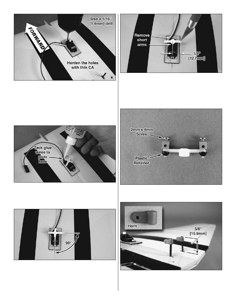
3. Remove the servo arm from the servo. Install your aileron
servo so that the output shaft is oriented forward. Route the
lead through the mounting plate on one side of the servo so
that it does not interfere with the servo arms. Note: You may
have to trim a notch for the wire to pass through. Use a 1/16"
[1.6mm] drill to make holes for the servo screws. Install the
screws and then remove them. Remove the servo and place a
drop of thin CA into each screw hole you just tapped.
❏
4. Reinstall the servo, making sure to route the servo lead
properly. To keep the servo lead clear of the servo arms, tack
glue the lead to the servo mounting plate using one drop of
medium CA.
❏
5. Using your radio system, center your aileron servo. Fit
your servo arm to the splined servo shaft and fi nd the position
on the splines that allows the two long arms to be 90° to the
servo case. Clip off the other two servo arms. To save time,
you can plug your other two servos into your receiver and
center them at this time.
❏
6. Use a #55 [1.3mm] drill to enlarge the two servo arm
holes that are 1/2" [12.7mm] from the center of the output
shaft. These are the outermost holes of the standard servo
arm. If you don’t have a #55 [1.3mm] drill bit, you can use
your hobby knife to carefully enlarge the hole until the screw-
lock pushrod connector pin fi ts.
❏
7. Install a screw-lock pushrod connector to each servo
arm and secure each one with a plastic retainer.
❏
8. Thread each torque rod horn onto the torque rods so
that the top of the horn is 5/8" [15.9mm] from the upper
surface of the wing with the aileron centered.