Apply the decals, Set the control throws – Great Planes PT-19 EP ARF - GPMA1149 User Manual
Page 19
19
❏
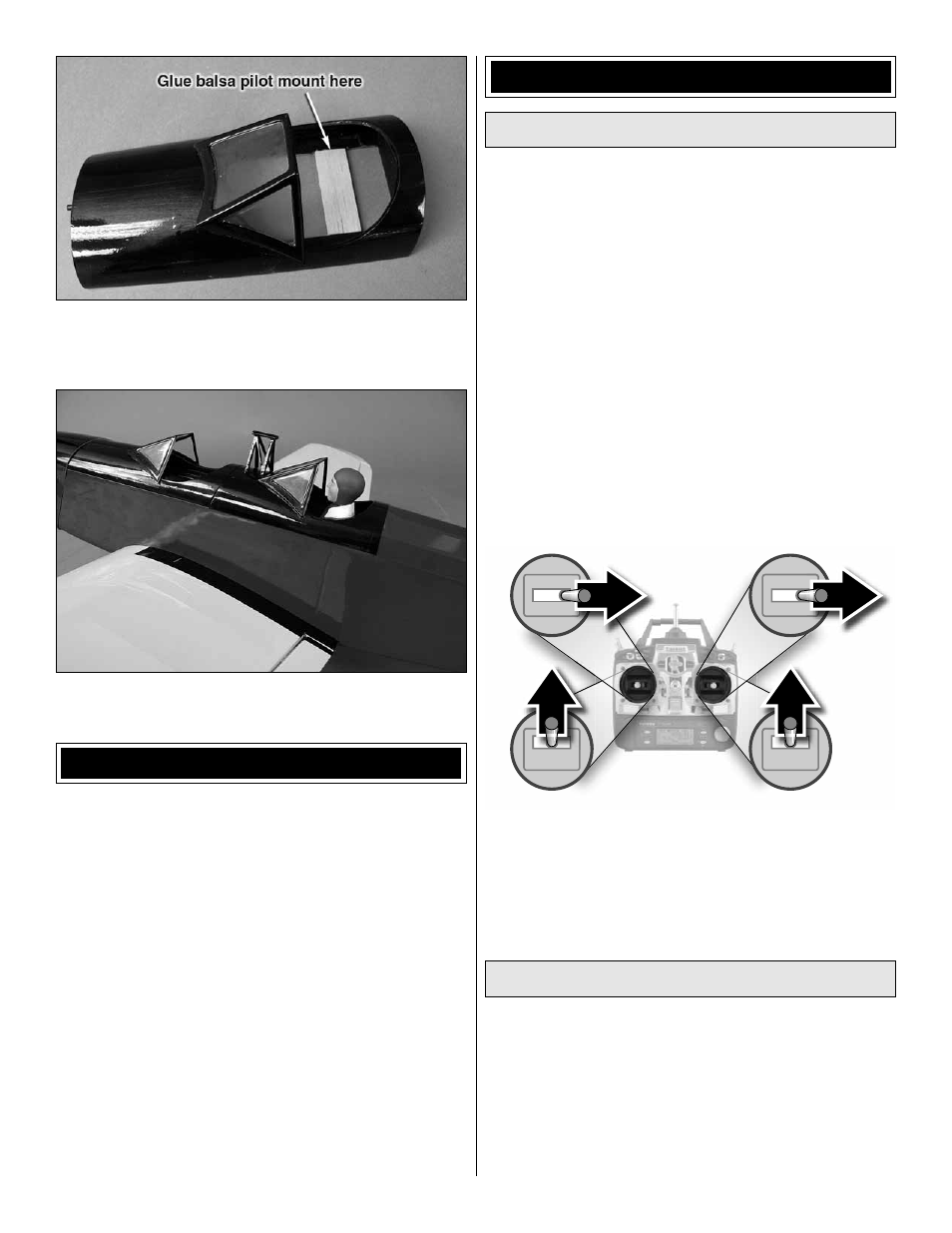
2. Position your pilot(s) where you want them. Remove the
hatch. Glue the 45mm x 15mm piece of balsa sheet in the
front cockpit as shown if you will be installing a pilot there.
❏
3. Glue the pilot(s) in each cockpit or use double sided
foam mounting tape (GPMQ4440).
APPLY THE DECALS
❏
1. Use scissors or a sharp hobby knife to cut the decals
from the sheet.
❏
2. Be certain the model is clean and free from oily
fi ngerprints and dust. Prepare a dishpan or small bucket with
a mixture of liquid dish soap and warm water—about one
teaspoon of soap per gallon of water. Submerse the decal
in the soap and water and peel off the paper backing. Note:
Even though the decals have a “sticky-back” and are not the
water transfer type, submersing them in soap & water allows
accurate positioning and reduces air bubbles underneath.
❏
3. Position decal on the model where desired. Holding the
decal down, use a paper towel to wipe most of the water
away.
❏
4. Use a piece of soft balsa or something similar to
squeegee remaining water from under the decal. Apply the
rest of the decals the same way.
GET THE MODEL READY TO FLY
Check the Control Directions
Warning: Once the battery is connected to the ESC, stay
clear of the propeller! Always stay behind the propeller!
❏
1. Turn on the transmitter, center the trims, and move the
throttle stick all the way down. Plug your airplane’s battery
into the ESC and check to see that all servo arms are
positioned properly. If necessary, remove the servo arms
from the servos and reposition them so they are centered.
Reinstall the screws that hold on the servo arms.
❏
2. If you have not already done so, center each of your
control surfaces so that they are all at zero defl ection. If you
need to make an adjustment, apply thread locking compound
to the locking screw threads and tighten all of the screw-lock
pushrod connectors.
Full Throttle
Rudder
Moves Right
Elevator Moves Down
Right Aileron
Moves Up
Left Aileron
Moves Down
4-CHANNEL RADIO SETUP
(Standard Mode 2)
❏
3. Make certain that the control surfaces and the throttle
respond in the correct direction as shown in the diagram.
If any of the controls respond in the wrong direction, use
the servo reversing in the transmitter to reverse the servos
connected to those controls. Be certain the control surfaces
have remained centered. Adjust if necessary.
Set the Control Throws
To ensure a successful fi rst fl ight, fl y your PT-19 set up only
according to the C.G. and control surface throws specifi ed in
this manual. The throws and C.G. are not arbitrary, but have
been determined through extensive testing and accurate
record-keeping. This provides you with the best chance for
success and enjoyable fi rst fl ights that should be surprise-
free. Additionally, the throws and C.G. shown are true, real
data which will allow the model to perform in the manner in
which it was intended when fl own by a pilot of the skill level