Great Planes PT-19 EP ARF - GPMA1149 User Manual
Page 14
14
❏
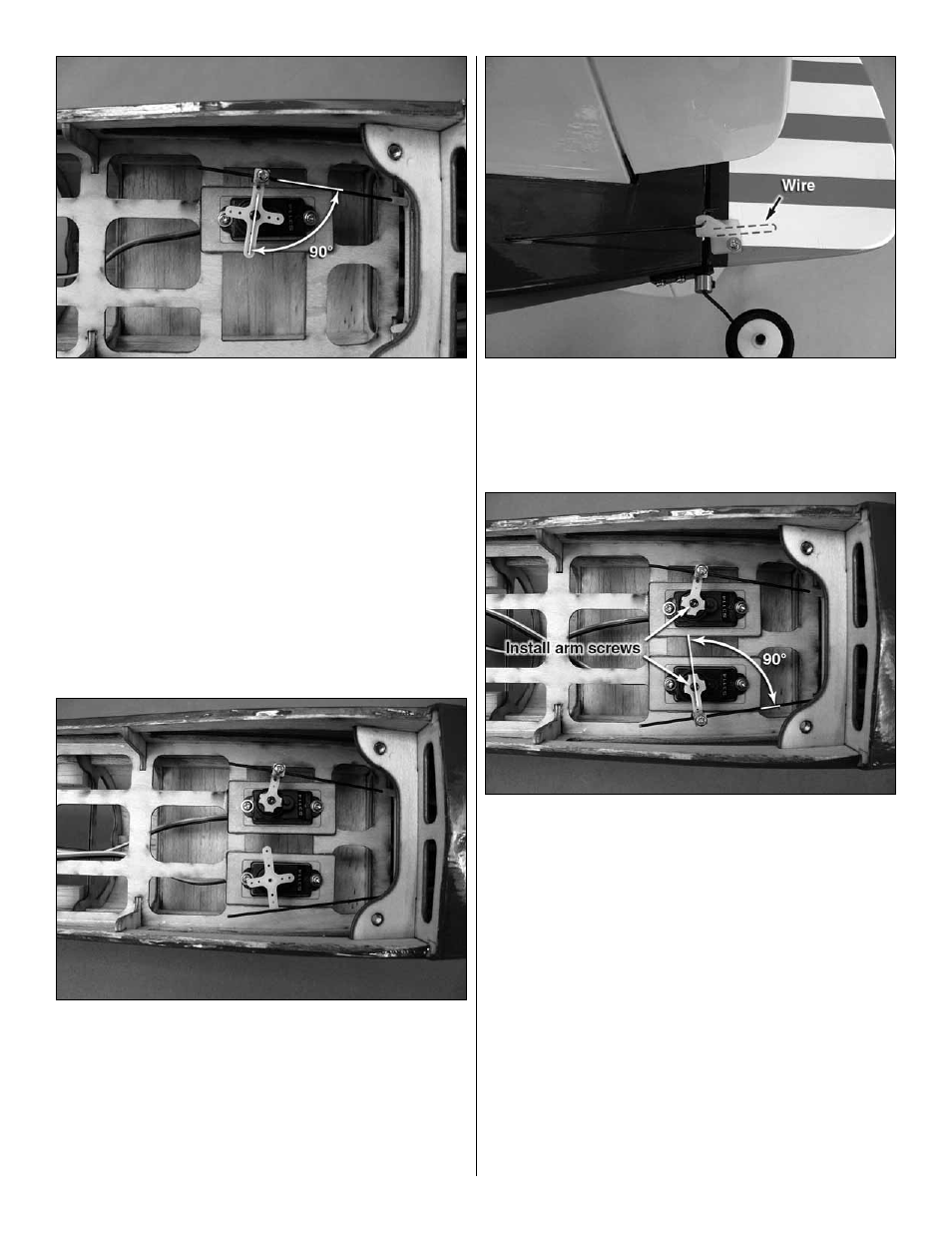
7. With your servo centered, fi t the standard size servo
arm to your servo so that the servo arm is 90° to the pushrod.
Use a #55 [1.3mm] drill to enlarge the outermost hole in the
servo arm or the hole that is 1/2" [12.7mm] from the center
of the output shaft. Install a screw-lock pushrod connector on
that arm using a plastic retainer. Clip off the unused arm and
install the servo arm screw.
❏
8. Center the elevator at zero defl ection and clip off the
excess pushrod wire about 3/4" [19.1mm] from the end of
the screw-lock pushrod connector. Apply a drop of thread
locking compound on the 2mm x 4mm pushrod locking
screw and tighten the locking screw with the elevator at
zero defl ection.
❏
9. Fit the other 1mm x 440mm Z-bend pushrod through
the pushrod guide tube on the left side of the fuselage. Use it
to help you install your rudder servo. Install the rudder servo
using a servo mounting plate and two servo screws.
❏
10. Fit the remaining control horn to the pushrod. Align
the horn over the rudder hinge line and vertically. Drill the
rudder using a 5/64" [2mm] drill. Install the control horn and
backplate using two 2mm x 10mm machine screws.
❏
11. Center your rudder servo and fi t a servo arm. Drill the
arm with a #55 [1.3mm] drill and install a screw-lock pushrod
connector on the outermost hole of the servo arm. Don’t
forget to install your servo arm screw!
❏
12. Apply a drop of thread locking compound to the 2mm
x 4mm pushrod locking screw. Center the rudder at zero
defl ection and tighten the locking screw. Trim off the unused
servo arms and the excess pushrod wire.