Balance the model (c.g.) – Great Planes PT-19 EP ARF - GPMA1149 User Manual
Page 20
20
for which it was intended. DO NOT OVERLOOK THESE
IMPORTANT PROCEDURES. A model that is not properly
setup may be unstable and possibly unfl yable.
The building steps earlier in this manual that show the
mechanical setup for the elevator, rudder, and aileron
linkages show you the best way to confi gure the linkages
to achieve the proper throws using Futaba micro servos
and a Futaba radio system. If you are using a different radio
system or you cannot achieve the proper control throws
using our suggested linkage confi guration, you may have to
install the pushrod connector in different holes on the servo
arms or the pushrod z-bends in different holes on the control
horns. Keep in mind that changing the throws mechanically
is preferred to changing them using your radio’s end-point
adjustment. End points should be used to “fi ne-tune” to get
the proper throws.
Use a Great Planes AccuThrow gauge, a ruler, or the
templates in the back of this manual to accurately measure
and set the control throw of each control surface as indicated
in the chart that follows. If your radio does not have dual
rates, we recommend setting the throws at the HIGH rate
setting. NOTE: The throws are measured at the widest part
of the elevators, rudder and ailerons.
These are the recommended control surface throws:
ELEVATOR
HIGH RATE
LOW RATE
1/2"
[13mm]
15 deg
Up
1/2"
[13mm]
15 deg
Down
1/4"
[6mm]
7 deg
Up
1/4"
[6mm]
7 deg
Down
RUDDER
7/8"
[22mm]
17 deg
Right
7/8"
[22mm]
17 deg
Left
1/2"
[13mm]
10 deg
Right
1/2"
[13mm]
10 deg
Left
AILERONS
3/8"
[10mm]
23 deg
Up
3/8"
[10mm]
23 deg
Down
1/4"
[6mm]
15 deg
Up
1/4"
[6mm]
15 deg
Down
Balance the Model (C.G.)
❏
1. At this stage the model should be in ready-to-fl y
condition with all of the systems in place including the motor,
landing gear, radio system, battery, and all hatches. Place
the battery in the battery compartment but do not connect it.
Fit the cowl in place.
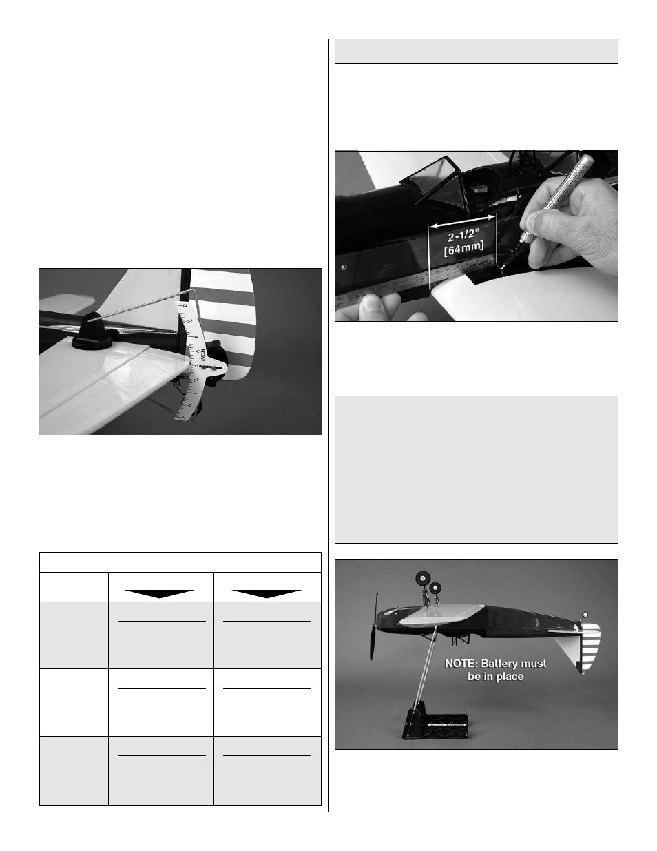
❏
2. Use a felt-tip pen or 1/8" [3mm]-wide tape to accurately
mark the C.G. on the top of the wing on both sides of the
fuselage at the wing root. The C.G. is located 2-1/2" [64mm]
back from the leading edge of the wing at the wing root.
This is where your model should balance for the fi rst fl ights.
Later, you may wish to experiment by shifting the C.G. up
to 3/8" [10mm] forward or 1/4" [6mm] back to change the
fl ying characteristics. Moving the C.G. forward may improve
the smoothness and stability, but the model may then
require more speed for takeoff and make it more diffi cult
to slow for landing. Moving the C.G. aft makes the model
more maneuverable, but could also cause it to become too
diffi cult to control. In any case, start at the recommended
balance point and do not at any time balance the model
outside the specifi ed range.
❏
3. With all parts of the model installed (ready to fl y) and a
battery pack in place (do not connect it), use a Great Planes
C.G. Machine, or place your fi ngers on the marks you made
and balance the model.