Traffic light control – Flintec II IPC User Manual
Page 28
FlintWeigh II IPC Technical Manual, Rev. 1.06 November 2011
Page 28 of 36
8.7.2.
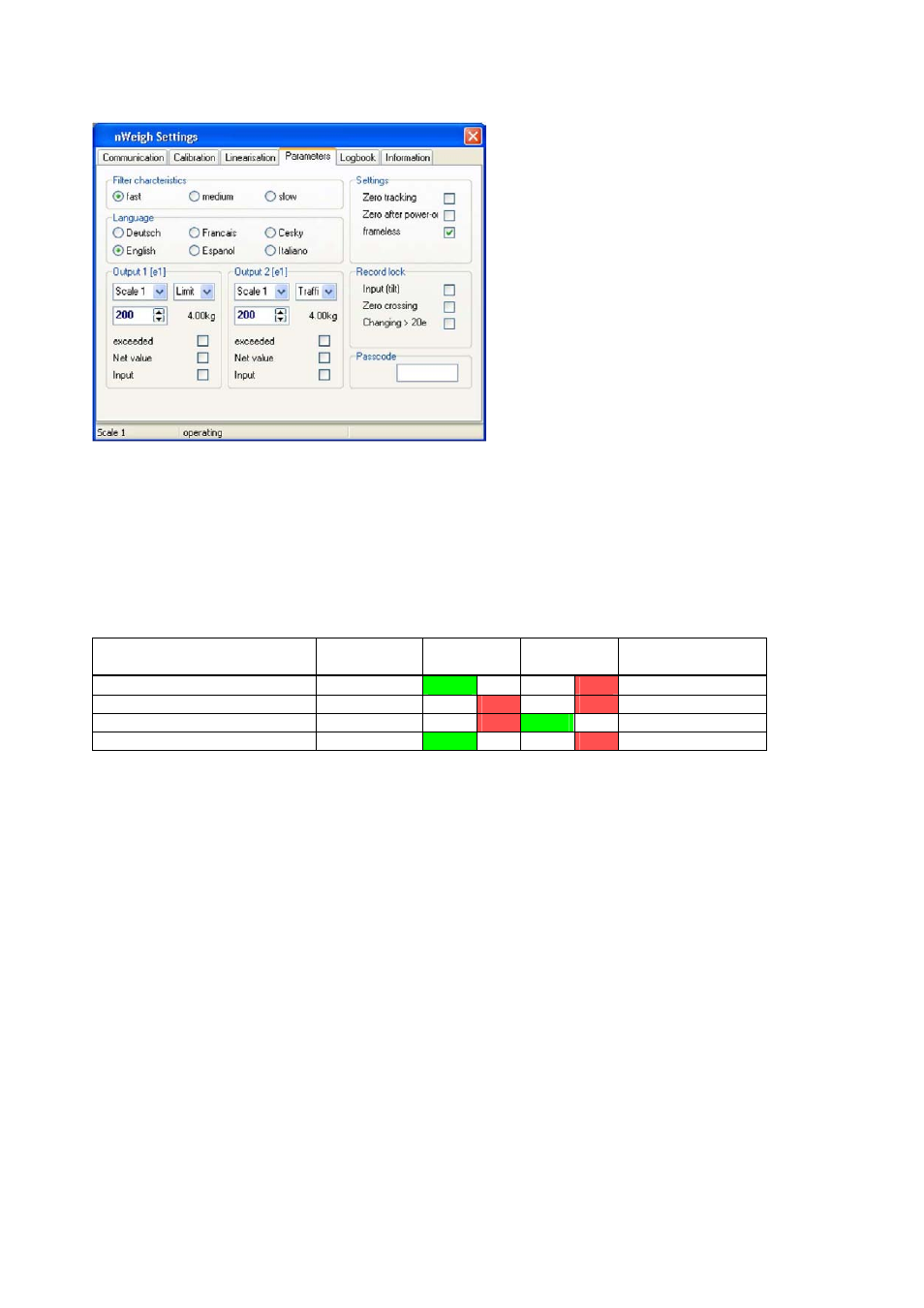
Traffic Light Control
Fig.8.13 Example for the traffic light control
The implementation of a traffic light control requires following setup:
1. Define the function “Limit“ for digital output 1
2. Define the function “Traffic Light” for digital output 2
3. The setpoint values for both outputs have to be defined to the same value in such a way, that the
system can reliably detect an “Empty scale”
A functional setup switches the outputs as follows (vehicle scale example):
Action/Status
Output 1
(“Empty”)
Entry
Exit
Output 2
(Weighing finalised)
Empty scale
A1 = 1
Green
Red
A2 = 0
Vehicle is on the scale
A1 = 0
Red
Red
A2 = 0
Weight recorded
A1 = 0
Red Green
A2 = 1
Empty scale
A1 = 1
Green
Red
A2 = 0