Digital corner correction – Flintec II IPC User Manual
Page 24
FlintWeigh II IPC Technical Manual, Rev. 1.06 November 2011
Page 24 of 36
Scale type:
Setting
Comment
Single-interval
The scale has exactly one weighing range with a constant
scale interval
Multi-range
The scale has 2 or 3 weighing ranges with different scale
intervals. If the current gros value of the measured weight falls
within the next weighing range and larger scale interval
(changeover threshold 1 and 2), then the larger scale interval
remains active until the scale will be unloaded and will return to
the zero point.
Multi-interval
The scale has 2 or 3 weighing ranges with different scale
intervals. The current value of the measured weight determines
the active weighing range and the active scale interval at any
time.
Scale interval 1/2/3: Step size of the display resolution for the scale respective the weighing range
Decimals:
Number of digits after the decimal point
Unit:
Weight unit for the displayed weight: g, kg, t or lb
No-motion range /
period:
Condition for a stable scale (no. of scale intervals, no. of measured values);
Default: 2d and 10 values in legal for trade applications; in industrial applications these
criteria may be modified
Max. capacity:
Maximum load of the scale (as a multiple of the scale interval e1)
Min. capacity:
Minimum load of the scale (as a multiple of the scale interval e1)
Test weight:
Weight of the calibration weight (as a multiple of the scale interval e1)
Changeover
threshold 1/2:
Only for multi-range / multi-interval scales:
Transition points for range or interval (as a multiple of the scale interval e1)
Important: For saving all scale parameter settings you have to close the window FlintWeigh II Settings
afterwards.
Now the weight display (Fig. 7.1) should show a random value.
The next step is the digital corner correction (see chapter 8.4.3).
8.4.3.
Digital Corner Correction
Important: After the digital corner correction the scale always requires a new calibration.
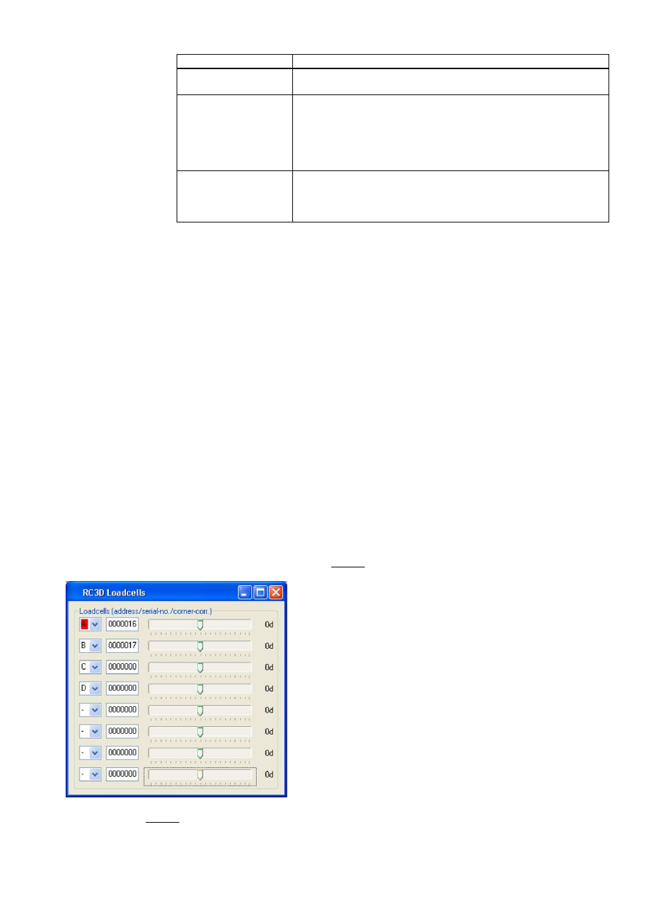
Fig.8.11 RC3D Load cells
Each corner (load cell) will be loaded one after the other with a
calibration weight (the calibration weight should be at least 10%
of max. capacity; better is 30% of max.capacity).
Using the slider the display value of the loaded load cell will be
corrected until the displayed value equals the calibration
weight.
The corner correction doesn’t depend on the sequence of the
loaded load cell, but a systematic course may spare time and
minimises the risk for errors (see chapter 8.4.1).
Hint: It may be meaningful to perform a calibration of the scale
and save the calibration data before the corner correction. This
optimises the display characteristics already before the corner
correction.
The next step is always the calibration of the scale (see chapter 8.5)