Optional use of digital outputs, Setpoints and limit monitoring – Flintec II IPC User Manual
Page 27
FlintWeigh II IPC Technical Manual, Rev. 1.06 November 2011
Page 27 of 36
8.7. Optional Use of Digital Outputs
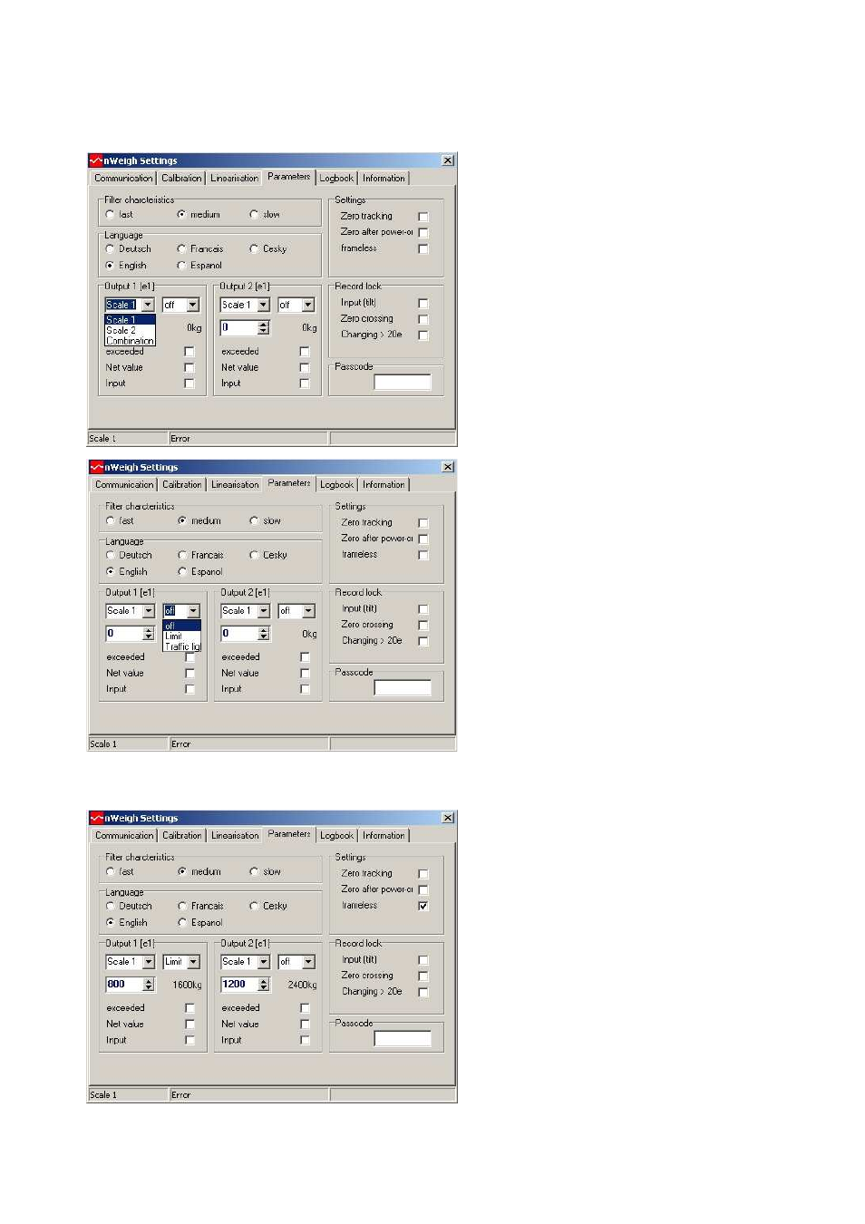
After opening the service functions (window FlintWeigh II Settings) and selecting the register “Parameters“, you
can assign a functionality to the digital outputs:
Fig.8.11 Register “Parameters“
for defining the digital outputs
Step 1: Select the source to control the output
Allowed settings are Scale 1, Scale 2 and
Combination.
Step 2: Assign a functionality to the output
Allowed settings are:
Setting
Function
“Off“
Without
“Limit“
Limit monitoring (see chapter 8.7.1)
“Traffic light“ Traffic light control (see chapter
8.7.2)
8.7.1.
Setpoints and Limit Monitoring
Fig.8.12 Example for the limit monitoring
1. Select the scale as the source
2. Select the function “Limit“
3. Define the weight value as a multiple of interval
e; if the output shall follow the “Net value”, then
activate the associated check box
4. The output will be switched, if the “weight value
< Limit“. If the output shall show an inverse
logic, then activate the associated check box
“Exceeded”
5. By activating the check box “Input” you may use
the digital input as an additional switching
criteria for the limit monitoring: the setpoint
output will only be activated, if the digital input is
active, too