Wiring diagrams, Ac900 – FingerTec AdapTec Plus User Manual
Page 7
7
L
N
E
-V
+V
Power Supply/Power Input Module
AC110~240V
L - Live
N - Neutral
E - Earth
R
B
G
R
Red
B
Blue
G
Green
AdapTec Plus
Access Control/Power Output Module
To Battery Tamper Siren
EM
Output
Siren
Door
Wiegand
Switch
Output 12V
Voltage
Accept
Exit
Input
- + Input
12V
0V
GND WD0 WD1
Connection
Points
GND
PWR
GND
WD0
WD1
DC 12V
Rechargeable
Backup
Battery
Connection
Points
Release
Button
EM +
Lock -
Emergency 2
Break
Glass (NC) 3
ON-OFF C
Key Switch
(NC) D
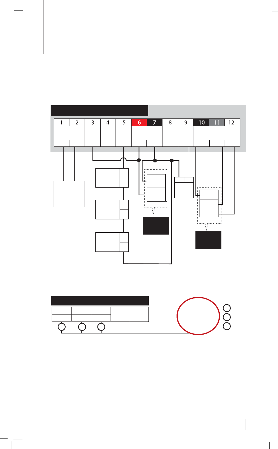
WIRING DIAGRAMS
AC900
FUNCTION •
Access Control Only or Time Attendance
& Door Access
STEP 1 •
Connection Points
STEP 2 •
Connect AdapTec Plus to a Power Source
STEP 3 •
Turn on the power to use FingerTec AC900 for door access con-
trol only or for time attendance and door access control simultaneously
See also other documents in the category FingerTec Equipment:
- FMM-100 (38 pages)
- M2 (38 pages)
- AC900 Installation Guide (3 pages)
- R2 Installation Guide (3 pages)
- Q2 (49 pages)
- R2i Manual (1 page)
- R2c Manual (2 pages)
- R2c Installation Guide (3 pages)
- H2i Manual (24 pages)
- H2i Installation Guide (3 pages)
- AC800 (63 pages)
- TA100 (36 pages)
- R3 Manual (28 pages)
- R3 Installation Guide (3 pages)
- i-Kiosk 100 Plus Manual (97 pages)
- i-Kiosk 100 Plus Installation Guide (3 pages)
- i-Kiosk 100 Manual (30 pages)
- AC100C Manual (29 pages)
- i-Kiosk 100 Installation Guide (3 pages)
- Q2i Manual (29 pages)
- Q2i Installation Guide (3 pages)
- AC100C Installation Guide (2 pages)
- TA100C Installation Guide (2 pages)
- TA200 Plus Installation Guide (2 pages)
- TimeLine 100 Manual (24 pages)
- AC100 Plus (37 pages)
- TA300 (14 pages)
- TA300 (2 pages)
- TA100 DIY (56 pages)
- TA500 Manual (26 pages)
- TA500 Installation Guide (2 pages)
- H3i Manual (2 pages)
- H3i Installation Guide (2 pages)
- s-Kadex Manual (2 pages)
- s-Kadex Installation Guide (2 pages)
- Keylock 8800 Manual (16 pages)
- Keylock 7700 (18 pages)
- Keylock 6600 (1 page)
- Face ID 2 (FEM 600) Manual (32 pages)
- Face ID 2 (FEM 800) Manual (32 pages)
- Face ID 2 (FEM 600) Quick Start (3 pages)
- Face ID 2 Installation Guide (3 pages)
- Face ID 3 Manual (35 pages)
- Face ID 3 Installation Guide (3 pages)
- Face ID 4 Manual (28 pages)