EVCO EC6105 User Manual
Page 2
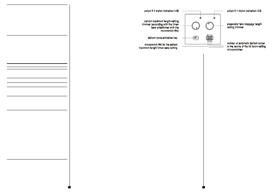
DEFROST MAXIMUM LENGTH SETTING
To modify the defrost maximum length value to position the microswitch M4 on the desired
scale and to rotate the trimmer TR2 as long as the arrow indicates the desired value (for in-
stance to set a defrost maximum length of twenty-seven minutes to position the microswitch
M4 in position B and to rotate the trimmer TR2 as long as the arrow indicates the notch
12/27).
ADDITIONAL INFORMATIONS
-
the modification of the defrost maximum length value has not immediate effect; to
obtain this effect it must not be executed during the course of the value
-
the course of the defrost maximum length value gets recorded each 10 minutes
and it is stored in a non volatile memory even if a lack of power supply happens;
when the power supply recovers the instrument reproposes the last setting stored
-
if the defrost stopping digital input is activated the instrument never activates a
defrost cycle.
EVAPORATOR FANS STOPPAGE LENGTH SETTING
To modify the evaporator fans stoppage length to rotate the trimmer TR1 as long as the arrow
indicates the desired value (for instance to set an evaporator fans stoppage length of eight
minutes to rotate the trimmer TR1 as long as the arrow indicates the notch 8).
ADDITIONAL INFORMATIONS
-
the modification of the evaporator fans stoppage length value has not immediate
effect; to obtain this effect it must not be executed during the course of the value
-
the course of the evaporator fans stoppage length value gets recorded each 10
minutes and it is stored in a non volatile memory even if a lack of power supply
happens; when the power supply recovers the instrument reproposes the last set-
ting stored.
CONFIGURABILITY
CONFIGURABILITY
CONFIGURABILITY
CONFIGURABILITY
CONFIGURABILITY
CONFIGURABILITY
MIN. MAX. U.M. ST.
DEFROST REGULATOR
0
7
---
3
number of automatic defrost cycles in the course of the
24 hours
It establishes the number of automatic defrost cycles that the instrument activates in the course
of the 24 hours.
0
30
min. 30
defrost maximum length
It establishes the defrost maximum length.
MIN. MAX. U.M. ST.
EVAPORATOR FANS REGULATOR ASSOCIATED TO THE
OUTPUT K 1
0
10
min. 10
evaporator fans stoppage length
It establishes the time that disable the output activation from the moment of the defrost end.
SIGNALS
SIGNALS
SIGNALS
SIGNALS
SIGNALS
SIGNALS
If the LED L1 is turned ON it means that the output K 1 is activated.
If the LED L2 is turned ON it means that the output K 2 is activated.
If the LED L2 flashes it means that an evaporator fans stoppage is running.
TECHNICAL DA
TECHNICAL DA
TECHNICAL DA
TECHNICAL DA
TECHNICAL DAT
TT
T
TA
A
A
A
A
TECHNICAL DATA
Case:
plastic grey (PP0), self-extinguishing.
Size:
53 x 90 x 58 mm (2.08 x 3.54 x 2.28 in., 3 DIN modules).
Installation:
on DIN EN 50022 standard rail installation according with
DIN 43880 norms.
Type of protection:
IP 40.
Connections:
screw terminal blocks with pitch 7.5 mm (0.29 in., power
supply, digital input and outputs) for cables up to 2.5 mm²
(0.38 in.²).
Ambient temperature:
from 0 to +60 °C (+32 to +140 °F, 10 ... 90 % of not con-
densing relative humidity).
Power supply:
230 Vac or 115 Vac or 24 Vac, 50/60 Hz, 1.5 VA.
Insulation class:
II.
Digital inputs:
1 for the remote stopping of a defrost (5 V, 1 mA) with NC
contact.
Display:
output status indicators.
Outputs:
two 8 (2) A @ 250 Vac relays for evaporator fans (NO con-
tact) and defrost system (change-over contact) manage-
ment.
Defrost management:
interval, safety temperature and maximum length.
HOW TO ORDER
HOW TO ORDER
HOW TO ORDER
HOW TO ORDER
HOW TO ORDER
CODING SYSTEM
Instrument name:
EC 6-105.
Fixed:
D.
Desired power supply:
220 (230 Vac)
115 (115 Vac)
A24 (24 Vac).
Options:
custom configuration.
2
3