EVCO EC6PCT User Manual
Ec 6-pct
EC 6-PCT
EC 6-PCT
EC 6-PCT
EC 6-PCT
EC 6-PCT
Configurable current transmitter
Operating instructions
Release 1/00 of November the tenth 2000
Code EC 6-PCT DOC E001
File 6pcte.p65
IMPORTANT:
The use of this new instrument is easy; but for safety reasons, it is
important read these instructions carefully before the installation or
before the use and follow all additional informations.
It is very important keep these instructions with the instrument for future
consultations.
ENGLISH
GENERAL INFORMA
GENERAL INFORMA
GENERAL INFORMA
GENERAL INFORMA
GENERAL INFORMATIONS
TIONS
TIONS
TIONS
TIONS
WHAT IS THE USE
EC 6-PCT is a configurable current transmitter studied to be used with some of the devices
built by Every Control provided with serial port of which it is able to display and to convert the
acquired quantity in a 4-20 mA signal; through the keys present on the instrument frontal panel
it is possible to operate on other functions as the output current and the device software code
display.
EC 6-PCT is available in the 53 x 90 mm (2.08 x 3.54 in., 3 DIN modules) case and it is studied
for DIN standard rail installation.
GETTING ST
GETTING ST
GETTING ST
GETTING ST
GETTING STAR
AR
AR
AR
ARTED
TED
TED
TED
TED
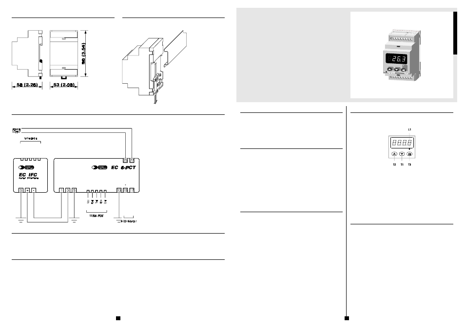
INSTALLATION
EC 6-PCT was studied for DIN EN 50022 standard rail installation according with DIN 43880
norms (the overall dimensions are related in Fig. 3, the fixing system suggested by the builder
is related in Fig. 4).
ADDITIONAL INFORMATIONS
-
verify if the using conditions (ambient temperature, humidity, etc.) are within the
limits indicated by the builder (see the chapter TECHNICAL DATA)
-
install the instrument in a location with a suitable ventilation, to avoid the internal
overheating of the instrument
-
do not install the instrument near surfaces that can to obstruct the air-grating (car-
pets, covers, etc.), heating sources (radiators, hot air ducts, etc.), locations sub-
ject to direct sunlight, rain, humidity, excessive dust, mechanical vibrations or
bumps, devices with strong magnetos (microwave ovens, big speakers, etc.)
-
according with the safety norms, the protection against possible contacts with
electrical parts and parts protected with functional insulation only must be ensured
through a correct installation procedure of the instrument; all parts that ensure the
protection must be fixed so that they can not be removed if not with a tool.
ELECTRICAL CONNECTION
EC 6-PCT is provided with three screw terminal blocks for cables up to 2.5 mm² (0.38 in.², for
the connection to the power supply, device serial interface and 4-20 mA output) and it is pro-
vided with one five poles single line female connector (for the connection to the CLONE
configurer/cloner and RICS supervision systems), located on the instrument frontal panel (the
connections to derive are related in Fig. 5 and they are checkable on the polyester label stuck
on the instrument case).
ADDITIONAL INFORMATIONS
-
if the instrument is brought from a cold to a warm location, the humidity may
condense inside the instrument; wait about an hour before supply the instrument
-
verify if the operating power supply voltage, electrical frequency and power of
the instrument correspond to the local power supply (see the chapter TECHNICAL
DATA)
-
do not supply more instruments with the same transformer
-
if the instrument is installed on a vehicle, its power supply must be derived di-
rectly from the battery of the vehicle
-
give the instrument a protection able to limit the current absorbed in case of
failure
-
the instrument remains connected to the local power supply as long as the termi-
nals 75 and 77 are derived to the local power supply, even if the instrument is
apparently turned off
-
do not try to repair the instrument; for the repairs apply to highly qualified staff
-
if you have any questions or problems concerning the instrument please consult
Every Control (see the chapter BUILDER DATA).
Fig. 1
f6-pct.wmf
USE
USE
USE
USE
USE
PRELIMINARY INFORMATIONS
After derived the connections related in Fig. 5, during the normal functioning the instrument
displays the acquired quantity by the device.
If an alarm should be active the instrument displays the alarm code flashing as long as the
cause that has given it does not disappear (see the chapter SIGNALS AND ALARMS).
EC 6-PCT is provided with some configuration parameters that get stored in a non volatile
memory and that permit to set the instrument according with one’s requirements (see the
chapter CONFIGURABILITY).
The 4-20 mA output signal is proportional to the acquired quantity in every point between the
acquired quantity values corresponding to 4 and 20 mA.
Pushing and releasing the key T1 the instrument displays the output current (the unit of meas-
ure is the thousandth of Ampere): after displayed the output current push and release the key
T1 (to the release of the key T1 the instrument displays the acquired quantity by the device
again, passed four seconds from the first release of the key T1 without operated with the keys
the instrument automatically turns out from the output current display procedure).
Keeping pushed for four seconds at least the key T2 the instrument displays the device soft-
ware code for four seconds (for instance if the instrument displays 2608, it means that the
device software code is 26 release 08).
CONFIGURATION PARAMETERS SETTING
Configuration parameters are arranged on two levels, to protect the most tricky settings against
undesirable violations and they are arranged in families that can be recognized through the
initial letter of the label.
To gain access to the first level keep pushed for two seconds at least the key T3 (passed two
seconds the instrument displays the label PA and the LED L1 turning ON).
To select a parameter of the first level push and release over and over the key T1 or T2 as long
as the instrument displays the label of the desired parameter.
To modify the parameter value push and release the key T3 (to the release of the key T3 the
instrument displays the actual value) and push and release over and over the key T1 or T2 as
long as the instrument displays the desired value (keeping pushed the key T1 or T2 the value
gets decreased or increased more quickly): after the modification push and release the key T3
(to the release of the key T3 the instrument displays the label of the parameter again); for the
four seconds following the first release of the key T3 or following the release of the key T1 or
T2 the instrument displays the set value and the LED L1 flashes to indicate that a configuration
parameter setting procedure is running (passed four seconds from the first release of the key
T3 or from the release of the key T1 or T2 without operated with the keys the instrument
automatically turns out from the configuration parameter setting procedure).
To turn out from the configuration parameters setting procedure keep pushed at the same time
for four seconds at least the keys T1 and T2 or keep pushed for two seconds at least the key T3
or do not operate with the keys for four seconds at least (time-out exit).
To gain access to the second level enter inside the first level and select the label PA.
Push and release the key T3 (to the release of the key T3 the instrument displays the actual
value) and push and release over and over the key T1 or T2 as long as the instrument displays
-19 (keeping pushed the key T1 or T2 the value gets decreased or increased more quickly):
after the modification push and release the key T3 (to the release of the key T3 the instrument
displays the label PA again) and keep pushed at the same time for four seconds at least the
1
4
Fig. 2
iu6pct.wmf
DIMENSIONAL DA
DIMENSIONAL DA
DIMENSIONAL DA
DIMENSIONAL DA
DIMENSIONAL DAT
TT
T
TA
A
A
A
A
OVERALL DIMENSIONS
The dimensions are expressed in millimetres and inches (third-scale drawing).
Fig. 3
ds63me.wmf
INST
INST
INST
INST
INSTALLA
ALLA
ALLA
ALLA
ALLATION
TION
TION
TION
TION
WITH THE FIXING SYSTEM SUGGESTED BY THE BUILDER
On DIN EN 50022 standard rail according with DIN 43880 norms (third-scale drawing).
Fig. 4
ms63m.wmf
ELECTRICAL CONNECTION
ELECTRICAL CONNECTION
ELECTRICAL CONNECTION
ELECTRICAL CONNECTION
ELECTRICAL CONNECTION
CONNECTIONS TO DERIVE
Instance of typical application.
BUILDER DA
BUILDER DA
BUILDER DA
BUILDER DA
BUILDER DAT
TT
T
TA
A
A
A
A
EVERY CONTROL S.r.l.
Via Mezzaterra 6, 32036 Sedico Belluno ITALY
Phone 0039/0437852468 (a.r.) Fax 0039/043783648
Internet addresses
e-mail: [email protected]
http://www.everycontrol.it
TO BE CAREFUL
This publication exclusively belongs to EVERY CONTROL and shall not be reproduced and distributed if not expressly authorized by the same EVERY CONTROL.
EVERY CONTROL does not assume any responsibility in order to the characteristics, to the technical data and to the possible mistakes related herein or deriving from the use of the same.
EVERY CONTROL can not be considered responsible for damages caused from the inobservance of the additional informations.
EVERY CONTROL reserves the right to make any modification without prior notice and at any time without prejudice the basic functioning and safety characteristics.
Fig. 5
c6-pcte.wmf