Table 2, Table 1 – EVCO EC3533 User Manual
Page 3
3
EC 3-533E 4/95
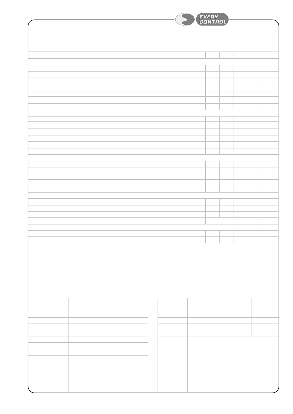
CONFIGURATION PARAMETERS
CODE PARAMETER
DESCRIPTION
MIN
MAX
U.M.
ST
(1) PA
PASSWORD
-55
+99
----
/
PROBE
/0
kind of probe
30 = 4-20 mA ; 31 = 0-20 mA
30
31
----
30
(1) /1
calibration (measure offset)
-9.0
+10
bar
0
/2
digital filter (speed response) 0=0s; 1=0.4s; 2=1.2s; 3=3.0s; 4=8.0s; 5=19.8s; 6=48.0s
0
6
----
3
/4
without leading zeros
0=NO; 1=YES
0
1
----
1
/5
with decimal point
0=NO; 1=YES
0
1
----
0
/6
start of scale for input 0-20 mA or 4-20 mA corrispondent to input's minimum value
-99
999
bar
see table 2
/7
end of scale for input 0-20 mA or 4-20 mA corrispondent to input's maximum value
-99
999
bar
see table 2
rA
PRESSURE REGULATOR
(1) rA0
regulator hysteresis (differential)
-99
+999 bar
-0.2
rA1
minimum setpoint admitted
-99
+999 bar
see table 2
rA2
maximum setpoint admitted
-99
+999 bar
see table 2
rA3
output action 0=active for high pressure (direct); 1=active for low pressure (reverse)
0
1
----
1
rA4
hysteresis selection
0=asymmetric; 1=symmetric
0
1
----
0
rA5
setpoint adjustement locking
0=unlocked; 1=locked
0
1
----
0
CA
OUTPUT ACTIVATION DELAY
CA0
output activation delay since instrument power-on
0
999
sec
0
CA1
after start delay
0
999
sec
0
CA2
after stop delay
0
999
sec
0
CA3
relay output status in case of probe failure
0=OFF; 1=ON
0
1
----
0
CA4
ON and OFF delay
0=no delay; 1=3sec
0
1
----
0
AA/Ab ALARM
AA=refered to alarm 1; Ab=refered to alarm 2
AA/Ab0 alarm hysteresis (differential)
1
+99
bar
0
AA/Ab1 alarm setpoint
-99
+999 bar
0
AA/Ab3 alarm disabling time since instrument power-on
0
999
min
0
AA/Ab4 alarm mode
see table 1
1
L
NETWORK CONNECTION
L1
instrument address
1
15
----
1
L2
instrument group
0
7
----
0
TABLE 2
connected
range par. /6 par. /7 par. rA1 par. rA2
transducer
(bar) (bar) (bar) (bar)
(bar)
EC PRS 00 -0.5÷7 -0.5
7
-0.5
7
EC PRS 01
0÷25 0
25
0
25
EC PRS 02
0÷30 0
30
0
30
EC PRS 03
0÷250 0
250 0
250
CUSTOM
configurable according to the needs
TABLE 1
parameter AA/Ab4 alarm mode
1
disabled
2
absolute minimum alarm
3
absolute maximum alarm
4
minimum alarm relative to setpoint 1
5
maximum alarm relative to setpoint1
6
minimum alarm relative to setpoint 1
with automatic enabling and recompute
7
maximum allarm relative to setpoint 1
with automatic enabling and recompute
notes
(1) = configuration parameter on LEVEL 1
N.B. On request, it is possible to configure the instrument with different unit of measure.
The transducers pressure ranges are to be considered as " relative to atmospheric pressure ";
the unit of measure is bar (1 bar = 0.1 MPa; 1 MPa = 10 bar).