EVCO EPK4LHX User Manual
C-pro 3 node kilo - programmable controllers
4.2
Meaning of connectors
The following charts show the meaning of the connectors of
the devices.
For further information look at chapter “TECHNICAL DATA”.
POWER
Power supply device (24 VAC/DC not isolated).
If the device is powered in direct current, it will be necessary
to respect the polarity of the power supply voltage.
If the device is connected to a devices network, it will be
necessary:
-
the power supply of the devices making the network is
galvanically isolated one another
-
the phase supplying the device is the same supplying all
the devices making the network.
Part Meaning
AC/+ power supply device:
-
if the device is powered in alternate current,
connect the phase
-
if the device is powered in direct current, con-
nect the positive pole
AC/-
power supply device:
-
if the device is powered in alternate current,
connect the neutral
-
if the device is powered in direct current, con-
nect the negative pole
ANALOG INPUTS
Analog inputs.
Part Meaning
GND
ground analog inputs
AI1
analog input 1, which can be set via configuration
parameter for PTC, NTC, Pt 1000 probes, 0-20 mA,
4-20 mA, 0-5 V ratiometric or 0-10 V transducers
AI2
analog input 2, which can be set via configuration
parameter for PTC, NTC, Pt 1000 probes, 0-20 mA,
4-20 mA, 0-5 V ratiometric or 0-10 V transducers
AI3
analog input 3, which can be set via configuration
parameter for PTC, NTC, Pt 1000 probes, 0-20 mA,
4-20 mA, 0-5 V ratiometric or 0-10 V transducers
AI4
analog input 4, which can be set via configuration
parameter for PTC, NTC or Pt 1000 probes
AI5
analog input 5, which can be set via configuration
parameter for PTC, NTC or Pt 1000 probes
AI6
analog input 6, which can be set via configuration
parameter for PTC, NTC or Pt 1000 probes
GND
ground analog inputs
+5V
power supply 0-5 V ratiometric transducers (5 VDC)
+24V power supply 0-20 mA, 4-20 mA and 0-10 V trans-
ducers (24 VAC)
DIGITAL INPUTS
Digital inputs.
Part Meaning
DI1
digital input 1 (24 VAC/DC, 50/60 Hz or 2 KHz
optoisolated); the frequency can be set with the
development environment UNI-PRO 3
DI2
digital input 2 (24 VAC/DC, 50/60 Hz or 2 KHz
optoisolated); the frequency can be set with the
development environment UNI-PRO 3
DI3
digital input 3 (24 VAC/DC, 50/60 Hz optoisolated)
DI4
digital input 4 (24 VAC/DC, 50/60 Hz optoisolated)
DI5
digital input 5 (24 VAC/DC, 50/60 Hz optoisolated)
COM common digital inputs
EVCO S.p.A. | Code 104CP3NKE113 | Page 1 of 2 | PT 46/14
c-pro 3 NODE kilo - Programmable controllers
GB
ENGLISH
IMPORTANT
Read this document carefully before installing and using the device and follow all the additional information; keep this
document close to the device for future consultations.
For further information consult the hardware manual.
The device must be disposed according to the local legislation about the collection for electrical and electronic
equipment.
1
INTRODUCTION
1.1
Introduction
c-pro 3 NODE kilo is a range of programmable controllers for applications in refrigeration and air conditioning sectors.
The controllers have a considerable number of inputs and outputs; they allow to realize a flexible, modular and expandable
control devices network.
The variety of available communication ports (RS-485, CAN, USB and Ethernet) and supported communication protocols
make easier the integration of the devices in systems.
The application software can be realized through the UNI-PRO 3 development environment for programmable controllers.
4
ELECTRICAL CONNECTION
4.1
Connectors
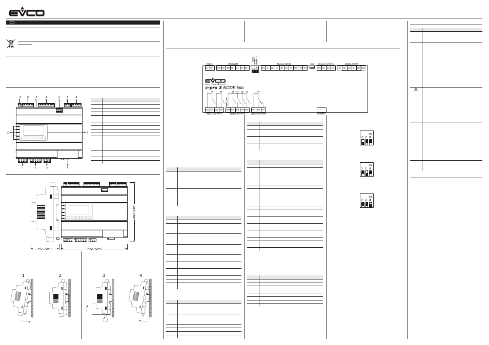
The following drawing shows the connectors of the devices.
The following chart shows the meaning of the parts of
the devices.
Part Meaning
1
digital outputs K1 and K2
2
digital outputs K3, K4, K5 and K6
3
digital output K7
4
MODBUS TCP, Web Server Ethernet port
5
display and keyboard (not available in the blind
versions)
6
digital inputs
7
analog outputs
8
USB port
9
analog inputs
10
micro-switch to plug in the CANBUS CAN port
line termination, the MODBUS master/slave
RS-485 port line termination and the MODBUS
slave RS-485 port line termination
11
MODBUS slave RS-485 port, MODBUS master/
slave RS-485 port and CANBUS CAN port
12
power supply
13
signalling LEDs
5
SIGNALINGS
5.1
Signalings
LED
Meaning
ON
LED power supply
if it is lit, the device will be powered
if it is out, the device will not be powered
RUN LED run
if it is lit, the application software will be com-
piled and running in release modality
if it flashes slowly, the application software will
be compiled and running in debug modality
if it flashes quickly, the application software will
be compiled, running in debug modality and
stopped in a breakpoint
if it is out:
-
the device will not be compatible with the
application software
-
the device will not be enabled to work with
the special ABL (Application Block Libraries)
LED system alarm
if it is lit, an alarm system not resettable via ap-
plication software will be running
if it flashes slowly, a system alarm with auto-
matic reset will be running
if it flashes very slowly, an access to the external
FLASH memory will be running
if it flashes quickly, a system alarm with manual
reset will be running
if it is out, no alarm system will be running
CAN LED CANBUS CAN communication
if it is lit, the device will be configured to commu-
nicate via CANBUS CAN with another device but
the communication will not have been set up
if it flashes slowly, the CANBUS CAN communica-
tion will have been set up but it will not be com-
pletely correct
if it flashes quickly, the CANBUS CAN communi-
cation will have been set up and will be correct
if it is out, no CANBUS CAN communication will
be running
L1
LED auxiliary
the operation of this LED can be set with the de-
velopment environment UNI-PRO 3
6
TECHNICAL DATA
6.1
Technical data
Purpose of control: operating control device.
Construction of control: incorporated electronic device.
Box: self-extinguishing grey.
Heat and fire resistance category: D.
Size: 142.0 x 128.0 x 60.0 mm (5.590 x 5.039 x 2.362 in;
W x H x D); 8 DIN modules.
Size refers to the device with the extractable screw termi-
nal blocks properly plugged.
Method of mounting control: on DIN rail 35.0 x 7.5 mm
(1.377 x 0.295 in) or 35.0 x 15.0 mm (1.377 x 0.590 in).
Degree of protection:
-
IP20 on the whole
-
IP40 the front.
Connections:
-
only male removable screw connection terminal blocks
with pitch 3.5 mm (0.137 in) for conductors up to
1.5 mm² (0.0028 in²): power supply, analog inputs,
digital inputs, analog outputs, MODBUS slave RS-485
port, MODBUS master/slave RS-485 port and CANBUS
CAN port
-
only male removable screw connection terminal blocks
with pitch 5.0 mm (0.196 in) for conductors up to
2.5 mm² (0.0038 in²): digital outputs
-
A type USB connector: USB port
-
RJ45 F telephone connector: MODBUS TCP, Web Server
Ethernet port.
The maximum lengths allowed for the connecting cables
are the following:
-
power supply: 100 m (328 ft)
-
analog inputs: 100 m (328 ft)
-
power supply transducers: 100 m (328 ft)
-
digital inputs: 100 m (328 ft)
-
PWM analog outputs: 1 m (3.280 ft)
-
0-20 mA, 4-20 mA and 0-10 V analog outputs: 100 m
(328 ft)
-
digital outputs (electromechanical relays): 100 m
(328 ft)
-
digital outputs (command for solid state relays):
100 m (328 ft)
-
MODBUS slave RS-485 port and MODBUS master/slave
RS-485 port: 1,000 m (3,280 ft); also look at MODBUS
specifications and implementation guides manual avail-
able on http://www.modbus.org/specs.php
3
SIZE AND INSTALLATION
3.1
Size
The following drawing shows the size of the devices (8 DIN modules); size is in mm (in).
2
DESCRIPTION
3.2
Installation
Installation is on DIN rail 35.0 x 7.5 mm (1.377 x 0.295
in) or 35.0 x 15.0 mm (1.377 x 0.590 in), into a switch-
board.
To install the devices operate as shown in the following
drawing.
To remove the devices remove possible extractable screw ter-
minal blocks plugged at the bottom first, then operate on the
DIN rail clips with a screwdriver as shown in the following
drawing.
To install the devices again press the DIN rail clips to the end
first.
3.3
Additional information for the installation
-
make sure the working conditions of the device (operat-
ing temperature, operating humidity, etc.) are in the limits
indicated; look at chapter “TECHNICAL DATA”
-
do not install the device close to heating sources (heat-
ers, hot air ducts, etc.), devices having big magnetos
(big speakers, etc.), locations subject to direct sunlight,
rain, humidity, dust, mechanical vibrations or bumps
-
according to the safety legislation, the protection against
possible contacts with the electrical parts must be en-
sured by a correct installation of the device; all the parts
which ensure the protection must be fixed so that you
can not remove them if not by using a tool.
ANALOG OUTPUTS
Analog outputs.
Part Meaning
GND
ground analog outputs
AO1
analog output 1, which can be set via configuration
parameter for PWM or 0-10 V
AO2
analog output 2, which can be set via configuration
parameter for PWM or 0-10 V
AO3
analog output 3, which can be set via configuration
parameter for 0-20 mA, 4-20 mA or 0-10 V
DIGITAL OUTPUTS
Digital outputs.
Part Meaning
CO1
common digital output 1
NO1
normally open contact digital output 1
according to the model:
-
3 res. A @ 250 VAC electromechanical relay
-
24 VAC/DC, 600 mA max. command for solid
state relay
CO2
common digital output 2
NO2
normally open contact digital output 2
according to the model:
-
3 res. A @ 250 VAC electromechanical relay
-
24 VAC/DC, 600 mA max. command for solid
state relay
CO3-6 common digital outputs 3... 6
NO3
normally open contact digital output 3 (3 res. A @
250 VAC electromechanical relay)
NO4
normally open contact digital output 4 (3 res. A @
250 VAC electromechanical relay)
NO5
normally open contact digital output 5 (3 res. A @
250 VAC electromechanical relay)
NO6
normally open contact digital output 6 (3 res. A @
250 VAC electromechanical relay)
CO7
common digital output 7
NO7
normally open contact digital output 7 (3 res. A @
250 VAC electromechanical relay)
NC7
normally closed contact digital output 7
CAN/RS-485
MODBUS slave RS-485 port, MODBUS master/slave RS-485
port and CAN CANBUS port.
The communication protocol of the MODBUS master/slave
RS-485 port can be set with the development environment
UNI-PRO 3.
Part Meaning
CAN+ positive pole CANBUS CAN port
CAN- negative pole CANBUS CAN port
GND
ground MODBUS slave RS-485 port, MODBUS mas-
ter/slave RS-485 port and CAN CANBUS port
A1/+ positive pole MODBUS master/slave RS-485 port
B1/-
negative pole MODBUS master/slave RS-485 port
A2/+ positive pole MODBUS slave RS-485 port
B2/-
negative pole MODBUS slave RS-485 port
USB
USB port.
ETHERNET
MODBUS TCP, Web Server Ethernet port.
4.2
Plugging in the CANBUS CAN port line termina-
tion
To plug in the CANBUS CAN port line termination, position
micro-switch 3 on position ON.
4.3
Plugging in the MODBUS master/slave RS-485
port line termination
To plug in the MODBUS master/slave RS-485 port line termi-
nation, position micro-switch 2 on position ON.
4.4
Plugging in the MODBUS slave RS-485 port line
termination
To plug in the MODBUS slave RS-485 port line termination,
position micro-switch 1 on position ON.
4.5
Polarizing the MODBUS master/slave RS-485
port
The polarization of the MODBUS master/slave RS-485 port
can be set via configuration parameter.
4.6
Polarizing the MODBUS slave RS-485 port
The devices are not able to polarize the MODBUS slave
RS-485 port; the polarization must be done by another de-
vice.
4.7
Additional information for electrical connection
-
do not operate on the terminal blocks of the device using
electrical or pneumatic screwers
-
if the device has been moved from a cold location to a
warm one, the humidity could condense on the inside;
wait about an hour before supplying it
-
make sure the power supply voltage, the electrical fre-
quency and the electrical power of the device correspond
to those of the local power supply; look at chapter “TECH-
NICAL DATA”
-
disconnect the power supply of the device before servic-
ing it
-
connect the device to a RS-485 devices network using a
twisted pair
-
connect the device to a CAN devices network using a
twisted pair
-
position the power cables as far away as possible from
the signal cables
-
do not use the device as safety device
-
for the repairs and for information about the device please
contact the EVCO sales network.
Description
The following drawing shows the aspect of the devices.