Dynaflite DYFA3040 User Manual
Page 11
5. Cut and fit the ribs from the remainder of
the 3/16" x 3/8" x 24" balsa. Cut the longer ribs
first. When satisfied with the fit, glue them into
position.
Note: It is important that the ribs fit the LE and
TE well. It is not important that each rib fit the
exact location shown on the plan.
Q 6. Remove the fin from the plan. Sand the top
and bottom surfaces flat and even. Use care not
to gouge any of the ribs.
FIN SHEETING
LEFTOVER
STAB SHEETING
SCRAP
SHEETING
1/16" X 3" X 10-1/2"
BALSA SHEETING
LJ 7. Sheet the fin with 1/16" x 3" x 30" balsa on
both sides. Do this with the fin flat on your
building board and use care not to twist it as
you glue the sheeting into place.
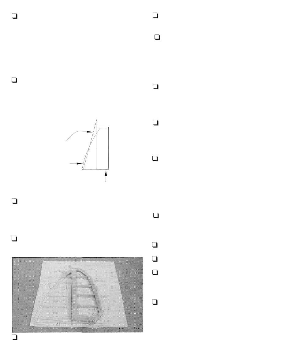
Q 8. Rough sand the fin to the shape shown in
the cross-section.
Q 9. Cut the rudder leading edge from 1/2" x
15/16" x 18" balsa and pin it to the plan.
Q 10. Cut the rudder base from the rest of the
1/2" x 15/16" balsa. Glue and pin it into place.
I—I 11. The rudder tip leading edge is built up
from three laminations of die-cut 1/8" balsa
pieces, for a total thickness of 3/8". Glue the
three pieces together and pin them in place on
the plan, using some leftover 1/16" balsa shims
where shown.
Q 12.The rudder trailing edge is built from two
laminations of die-cut 1/8" balsa pieces, for a
total thickness of 1/4". Build two of these
assemblies using the plan as a reference.
Q 13. Cut some shims from leftover 1/8" balsa
and place them in position over the plan at the
TE where shown. Pin and glue the TE into
position.
Q 14. Cut and fit the ribs from 3/16" x 1/2" x 18"
balsa. Cut the longer ribs first. When satisfied
with the fit, glue them into position.
Note: It is important that the ribs fit the LE and
TE well. It is not important that each rib fit the
exact location shown on the plan.
Q 15. Remove the rudder from the plan and
rough sand it to the shape shown in the cross-
section.
Q 16. Tack glue the rudder to the fin.
Q 17. Sand the assembly to its final shape.
Q 18. Separate the rudder from the fin. Sand
the trailing edge of the fin flat as shown on the
cross-section on the plan.
Q 19. Mark the centerline of the fin trailing edge
and rudder leading edge along their entire
length. Using the cross-section on the plan as a
reference, sand the rudder leading edge to
the "V" shape shown. Make sure the angle of
the "V" is enough to allow for the full left and
right movement of the rudder.
11