Dynaflite GPMA0090 Butterfly User Manual
Page 25
25
B.
Generally, all sport models require only two
fuel lines: one that goes to the
top of the tank
for pressure or a vent and another for fuel pick-
up. Some models use a third line for a fuel fi ller
valve but this is not required on your Butterfl y. To
fi ll the tank, simply disconnect the pick-up line
from the carburetor and fi ll through it. When the
tank is full fuel will fl ow through the vent line that
is connected to your muffl er (disconnect the line
from the muffl er while fueling).
C.
The line that comes from the top of the tank
and is connected to the muffl er is the vent or
“pressure” line. Exhaust pressure from the
muffl er pressurizes the fuel tank for reliable
fuel fl ow. Should the pressure line ever become
disconnected, You will notice that the engine will
run lean due to the decrease in pressure which
causes less fuel fl ow (by the way, “
lean
” means
not enough fuel and “
rich
” means too much fuel).
D.
Frequently inspect your fuel lines for small
holes and replace them annually. Undetected
holes in fuel lines cause air or fuel leaks and
can cause a variety of engine running or starting
problems.
❏
17.
Position the fuel tank in the fuselage, then
drill 1/4" holes (or 15/64" for precision) in the fi rewall
for the fuel lines. Plan carefully where you drill the
holes so the engine mount will not interfere with
the fuel lines. Temporarily connect the fuel lines
to make sure the holes are in the proper location.
❏
18.
Drill a 3/16" hole in the fi rewall for the throttle
pushrod guide tube.
❏
19.
Temporarily install the 12" pushrod tube
(you saved from the remainder of the elevator and
rudder guide tubes) in the fuselage through the
fi rewall, past the fuel tank and through the hole
you previously drilled in F-6.
❏
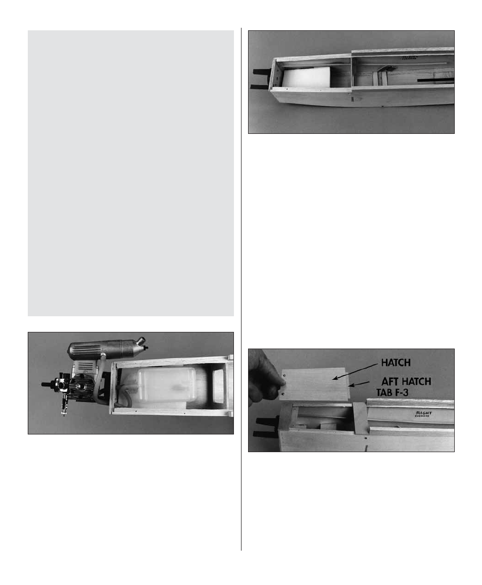
20.
Remove the fuel tank, engine and fuel lines.
Glue the
forward fuselage tops F-3A
and
F-2A
in position with medium CA. Glue the
forward
hatch
tab F-3
to the bottom of F-3A. (See photo
at step 23.)
❏
21.
Cut or sand a bevel to one end of the
hatch
so it fi ts between F-3A and F-2A.
❏
22.
Glue the
aft hatch tab
to the hatch with
medium CA, then position the hatch and drill two
1/16" holes through the hatch and the forward
hatch tab.
❏
23.
Remove the hatch, then enlarge the holes
in the hatch only
with a 3/32" drill. Fasten the
hatch to the fuselage with two #2 x 3/8" screws,
then sand the sides of the hatch so they are even
with the fuselage.