Dynaflite GPMA0090 Butterfly User Manual
Page 23
23
❏
2.
Cut two 36" outer pushrod guide tubes to a
length of 24". Use 150-grit sandpaper to carefully
(so you do not snap them in two) roughen the
outside of the tubes so glue will stick to them. Save
the remaining 12" from one of the tubes for the
throttle pushrod guide tube.
❏
3.
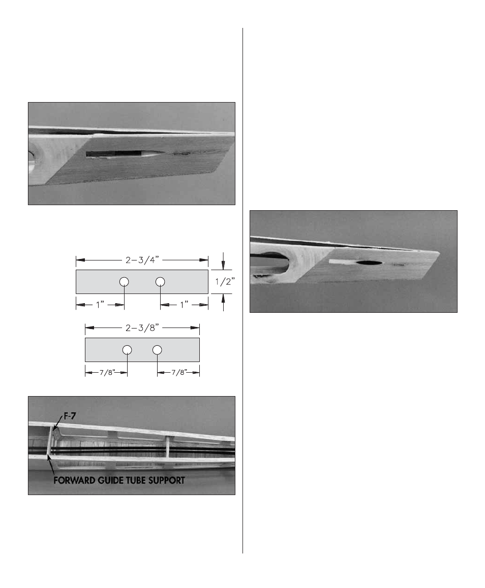
Use a small, round wood fi le or a hobby knife
to bevel the aft edge of the slot in both fuselage
sides for the pushrod guide tubes.
Forward
Aft
❏
4.
Make a
forward
and
aft pushrod guide tube
support as shown in the sketch from leftover 1/4"
x 3/8" balsa. Position the aft support as shown in
the photo and position the forward support in front
of F-7. Insert the pushrod guide tubes.
❏
5.
Position the guide tubes so approximately 1/2"
protrudes from the slots at the rear of the fuselage.
Use medium CA to glue
only the aft support
in
position but do not glue the tubes to the support
and do not glue the front support in position until
instructed to do so.
❏
6.
Glue the pushrod guide tubes in the slots in the
rear of the fuselage with thin CA, then fi ll the slots
with HobbyLite fi ller or glue the tubes in the slots
with epoxy and microballoons. If you’ve never heard
of microballoons, it’s a powder made of microscopic
glass “balloons” that you mix with epoxy to use as
a fi ller or adhesive. The microballoons and epoxy
mixture is harder to sand than regular fi ller so it
is used only where structural strength is required.
❏
7.
Sand the fi ller and pushrod tubes with your
bar sander and 150-grit sandpaper so they are
fl ush with the fuselage sides.
❏
8.
Glue the pushrod tubes to only the aft support.
❏
9.
Use your bar sander to sand the tops of the
fuse sides so the formers, the triangle side stringers
and the fuse sides are all even.
❏
10.
Position the stab on the fuselage so the
trailing edge is 1" aft of the end of the fuse (as
shown on the plan). Use a ballpoint pen to mark
the location of the stab leading edge on the top of
the fuse sides and triangle stringers.