DLE 20 User Manual
Page 8
8
on the bolts before securing the nuts onto the bolts on the rear of
the fi rewall. Be sure to use Threadlocker on the screws holding the
engine mount to the fi rewall.
3. Place the engine on the engine mount and at the recommended
distance from the fi rewall and test-fi t the cowling on the aircraft to
verify the distance. When you’re satisfi ed with the engine’s position,
mark the location of the four holes on the mount.
4. Remove the engine from the mount. Drill and tap the engine mount
at the position of the four mounting holes. Use an appropriate size
screw (we used (2)1-1/4” and (2) 1” 8-32 thread SHCS). It’s a good
idea to drill and tap all the way through the mounting beams in
order to secure each screw with a lock nut.
5. Secure the four screws with lock washers, fl at washers, and lock nuts.
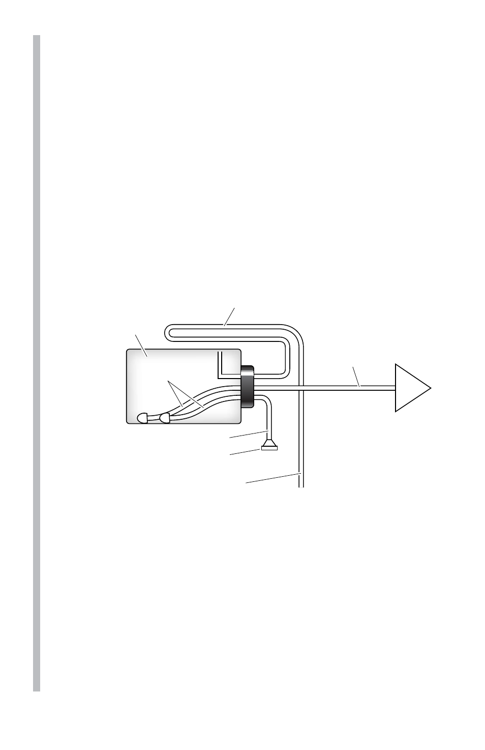
Drain/Vent Pressure Relief Line
Route to top-front of fuel tank interior,
to prevent siphoning.
Carb
Clunk Lines
Fuel Tank
Plug
Supply Line
to Carburetor
Fuel fill line
This line must be extended
to exit the bottom of the aircraft.
6. Install the fuel tank in the airframe. Use only gasoline-safe fuel lines
and a gasoline safe stopper. One line should go to the carburetor and
the other is to be used as a vent (a vent line is simply an open ended
fuel line from the fuel tank which exits the engine compartment or
the fuselage; most vent lines exit at the bottom of the fi rewall).You
can fi ll the tank by using the carburetor line as fi ll line if you have
access to it or install a third line to be used as fi ll line. Installing a
third line is the cleanest and easiest way to add fuel. An alternative
fueling set up is a 2-line system with a T-fi tting approved for gasoline
use. Be sure to use a fi ller plug with either a 2 line or 3 line set-up.
It is a good idea to add an extension to the vent line as shown, that
goes up and to the rear of the tank. This helps to avoid draining fuel
from the tank when the model is pointed down.