Installing the dle-20 on your airplane – DLE 20 User Manual
Page 7
7
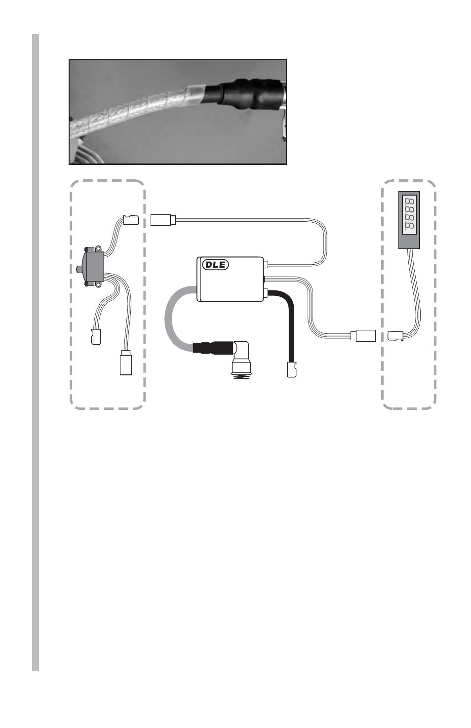
7. Secure all connections with heat shrink tubing (not supplied).
8. Install the silicone
ignition wire cover over
the ignition wire.
9. Install the spark plug
into the engine head (7-8
lbs torque).
Ignition Wire
(To Spark Plug)
Ignition Control Switch Wire
(To On/Off Switch)
Pick-Up
Sensor Wire
(To Sensor On Engine)
Tachometer
Lead/
RPM
Signal
Out-Put
ELECTRONIC IGNITION
SYSTEM
Battery
Lead
Charge
Lead
Switch
(Not included)
Optional
Tachometer
(Not included)
Installing the DLE-20 on Your Airplane
Note: The DLE-20 must be installed on at least a 6mm [1/4”] fi rewall.
The fi rewall must be securely glued to the airplane. Use triangle
stock and pin the fi rewall with hardwood dowels to reinforce the
fi rewall glue joints. Never install the DLE-20 onto a fi rewall thinner
than specifi ed because it may fail due to the power of the engine.
1. Select an engine mount. A two-piece engine mount that does not
interconnect or overlap at the fi rewall is preferred for the DLE-20, like
the Dubro Vibration Reducing Engine Mount 1.20-1.80 (DUBG1307).
2. Before securing the engine mount to the fi rewall, test fi t the engine
onto the mount and place the mount onto the fi rewall. Use this
positioning to create an engine mounting template. Use the template
to drill the mounting holes in the locations on the fi rewall. Note: A
Template for mounting the DUBG1307 is provided on the back of
this manual. Press the blind nuts into the rear of the fi rewall. If you
choose to use regular nuts or lock nuts be sure to place washers