Basic i/o, Fmc-hpc connector, Quality assurance – Digilent 410-256P-KIT User Manual
Page 6: Spartan-6
FMC Carrier-S6 Reference Manual
www.digilentinc.com
page 6 of 7
Copyright Digilent, Inc. All rights reserved. Other product and company names mentioned may be trademarks of their respective owners.
Spartan-6
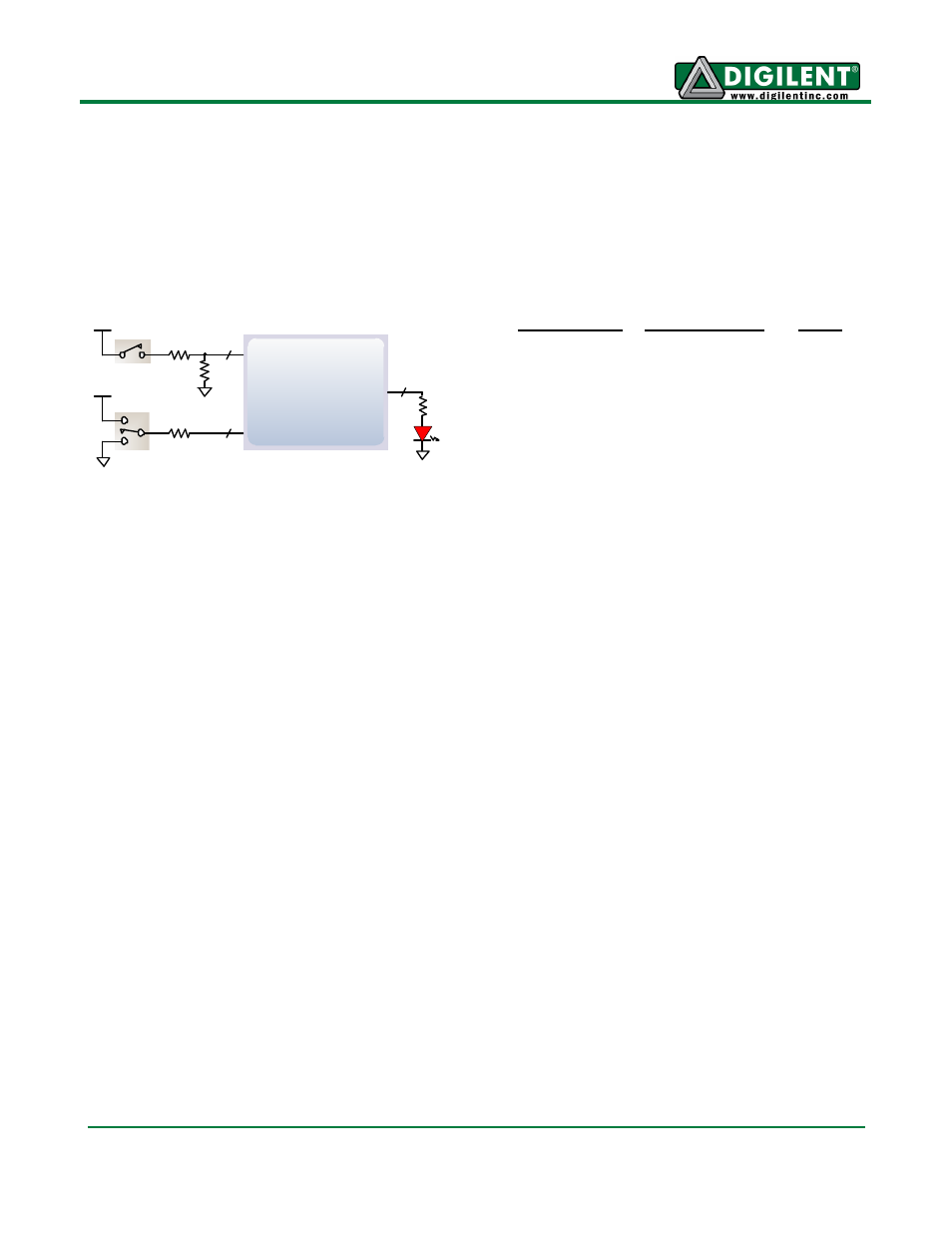
Slide Switches
10K
10K
10K
LEDs
390
2
2
2
Pushbuttons
Basic I/O
The FMC Carrier - S6 board includes two pushbuttons, two slide switches, and two LEDs for basic
digital input and output. The buttons and slide switches are connected to the FPGA via series
resistors to prevent damage from inadvertent short circuits. The high efficiency LED anodes are
connected to the FPGA via 390-ohm resistors, and they will brightly illuminate with about 1mA of
current when a logic high voltage is applied to their respective I/O pin.
FMC-HPC Connector
A single high-pin count (HPC) FMC slot is provided on the FMC Carrier
– S6 to support a large
ecosystem of plug-in modules. The FMC exposes 126 single-ended I/O, 102 of which can be
configured as 51 differential pairs. The FMC interface spans over 4 PL I/O banks (banks 0, 1, 2, and
Misc.). The FMC pin-out can be found in the FMC Carrier
– S6 General UCF file.
Quality Assurance
All FMC Carrier - S6 boards are 100% tested during the manufacturing process. If any device on the
FMC Carrier - S6 board fails test or is not responding properly, it is likely that damage occurred during
transport or during use. Typical damage includes stressed solder joints and contaminants in switches
and buttons resulting in intermittent failures. Stressed solder joints can be repaired by reheating and
reflowing solder and contaminants can be cleaned with off-the-shelf electronics cleaning products. If a
board fails test within the warranty period, it will be replaced at no cost. If a board fails test outside of
the warranty period and cannot be easily repaired, Digilent can repair the board or offer a discounted
replacement. Contact Digilent for more details.
Pushbuttons
Slide Switches
LEDs
BTNU: E4
SW0: U7
LD0: V15
BTND: F5
SW1: V7
LD1: N12