Oscillators/clocks, Usb-uart bridge (serial port) – Digilent 410-256P-KIT User Manual
Page 5
FMC Carrier-S6 Reference Manual
www.digilentinc.com
page 5 of 7
Copyright Digilent, Inc. All rights reserved. Other product and company names mentioned may be trademarks of their respective owners.
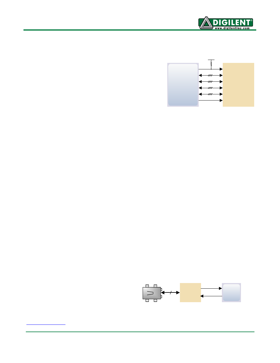
Flash Memory
The FMC Carrier - S6 board uses a 128Mbit Numonyx
N25Q128 Serial Flash memory device (organized as 16-bit
by 16Mbytes) for non-volatile storage of FPGA
configuration files. The SPI Flash can be programmed with
a .bit, .bin., or .mcs file using the Adept software. An FPGA
configuration file requires less than 12Mbits, leaving
116Mbits available for user data. Data can be transferred
from a PC to/from the Flash by user applications, or by
facilities built into the Adept software. User designs
programmed into the FPGA can also transfer data to and
from the ROM.
A simple demo image has been loaded into the Serial Flash during manufacturing. It connects the
User LEDs (LD0, LD1) to the User Switches (SW0, SW1). The image along with the project source is
available on the Digilent website.
Oscillators/Clocks
The FMC Carrier - S6 board includes a single 100MHz Oscillator connected to pin T9 (T9 is a GCLK
input in bank 2). The input clock can drive any or all of the four clock management tiles in the Spartan-
6. Each tile includes two Digital Clock Managers (DCMs) and one Phase-Locked Loop (PLL).
DCMs provide the four phases of the input frequency (0º, 90º, 180º, and 270º), a divided clock that
can be the input clock divided by any integer from 2 to 16 or 1.5, 2.5, 3.5... 7.5, and two antiphase
clock outputs that can be multiplied by any integer from 2 to 32 and simultaneously divided by any
integer from 1 to 32.
PLLs use Voltage Controlled Oscillators (VCOs) that can be programmed to generate frequencies in
the 400MHz to 1080MHz range by setting three sets of programmable dividers during FPGA
configuration. VCO outputs have eight equally-spaced outputs (0º, 45º, 90º, 135º, 180º, 225º, 270º,
and 315º) that can be divided by any integer between 1 and 128.
USB-UART Bridge (Serial Port)
The FMC Carrier - S6 includes an FTDI USB-UART bridge to allow PC applications to communicate
with the board using a COM port. Free drivers allow COM-based (i.e., serial port) traffic on the PC to
be seamlessly transferred to the FMC
Carrier
– S6 board using the USB
port at J3 marked UART. The FTDI
part delivers the data to the Spartan-
6 using a two-wire serial port with
software flow control (XON/XOFF).
Free Windows and Linux drivers can
be downloaded from
After the drivers are installed, I/O commands from the PC directed to the COM
port will produce serial data traffic on the T10 and Q10 FPGA pins.
T10
TXD
U10
Micro-USB
J3
“UART”
2
RXD
Spartan-6
FT232HQ
CS#
SDI/DQ0
SDO/DQ1
R15
R13
T13
V3
Spartan-6
SPI Flash
WP#/DQ2
HLD#/DQ3
T14
V14
SCK