Digilent DIO1 User Manual
Page 9
Digilent DIO1 Reference Manual
Digilent, Inc.
www.digilentinc.com
page 9 of 10
Copyright Digilent, Inc. All rights reserved. Other product and company names mentioned may be trademarks of their respective owners.
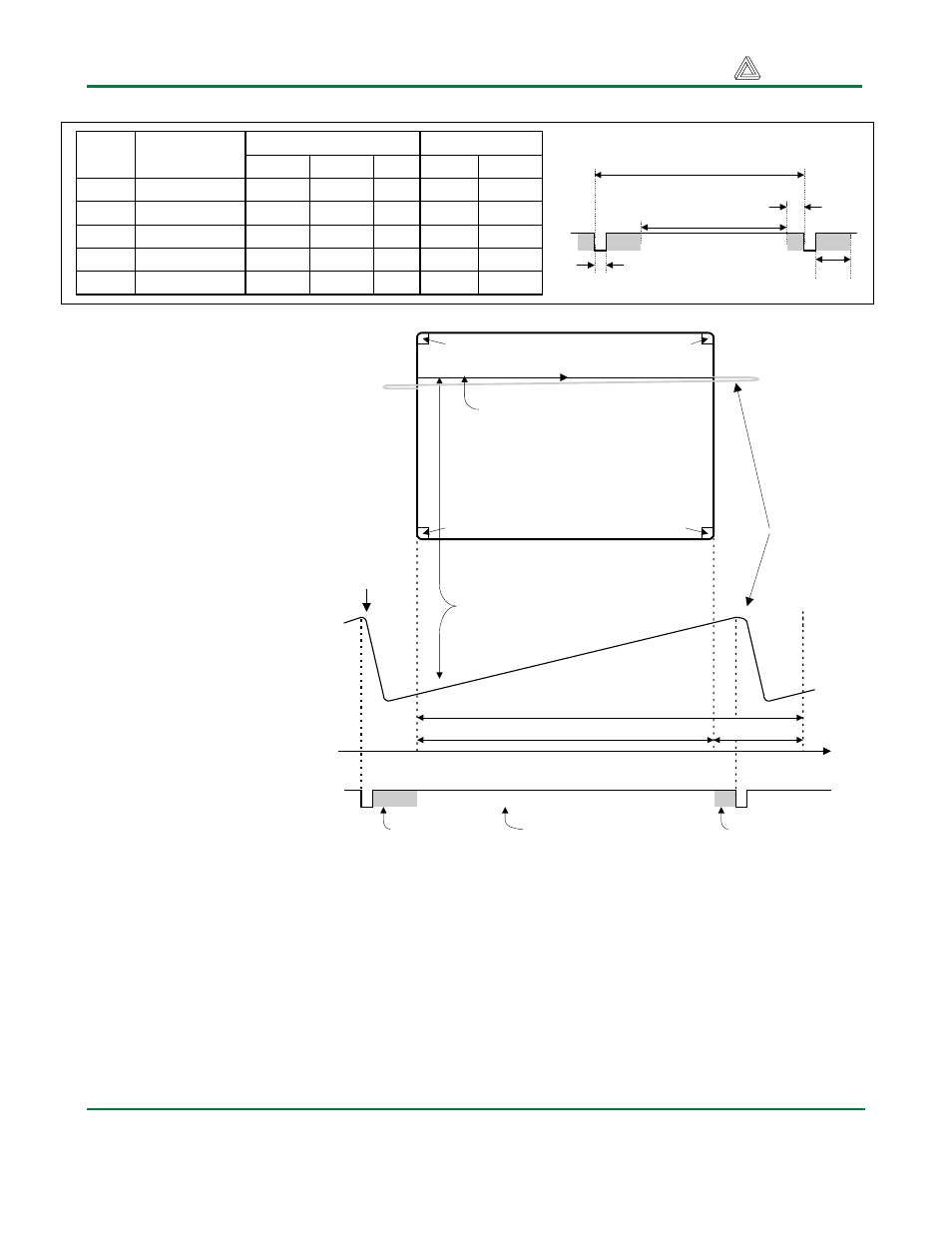
Current
through
horizontal
defletion
coil
Stable current ramp - information
displayed during this time
Retrace - no
information
displayed
during this
time
Total horizontal time
Horizontal display time
Horizontal sync signal
sets retrace frequency
retrace time
time
HS
"back porch"
"front porch"
VGA display
surface
640 pixels are displayed each time
the beam travels across the screen
pixel 0,639
pixel 0,0
pixel 479,0
pixel 479,639
data is applied to the
electron guns at the correct
time. Video data typically
comes from a video refresh
memory; with one or more
bytes assigned to each pixel
location (the DIO1 board
uses 3-bits per pixel). The
controller must index into
video memory as the beams
move across the display,
and retrieve and apply
video data to the display at
precisely the time the
electron beam is moving
across a given pixel.
The VGA controller circuit
must generate the HS and
VS timings signals and
coordinate the delivery of
video data based on the
pixel clock. The pixel clock
defines the time available
to display 1 pixel of
information. The VS signal
defines the “refresh”
frequency of the display, or the frequency at
which all information on the display is
redrawn. The minimum refresh frequency is a
function of the display’s phosphor and electron
beam intensity, with practical refresh
frequencies falling in the 60Hz to 120Hz range.
The number of lines to be displayed at a given
refresh frequency defines the horizontal
“retrace”
VGA Signal Timing
A VGA controller circuit decodes the output of
a horizontal-sync counter driven by the pixel
clock to generate HS signal timings. This
counter can be used to locate any pixel location
on a given row. Likewise, the output of a
vertical-sync counter that increments with each
HS pulse can be used to generate VS signal
timings, and this counter can be used to locate
T
S
T
disp
T
pw
T
fp
T
bp
T
S
T
disp
T
pw
T
fp
T
bp
Sync pulse time
Display time
VS pulse width
VS front porch
VS back porch
16.7ms
15.36ms
64 us
320 us
928 us
416,800
384,000
1,600
8,000
23,200
521
480
2
10
29
Symbol
Parameter
Time
Clocks Lines
Vertical Sync
32 us
25.6 us
3.84 us
640 ns
1.92 us
800
640
96
16
48
Clocks
Horizontal Sync
Time