Digilent DIO1 User Manual
Page 3
Digilent DIO1 Reference Manual
Digilent, Inc.
www.digilentinc.com
page 3 of 10
Copyright Digilent, Inc. All rights reserved. Other product and company names mentioned may be trademarks of their respective owners.
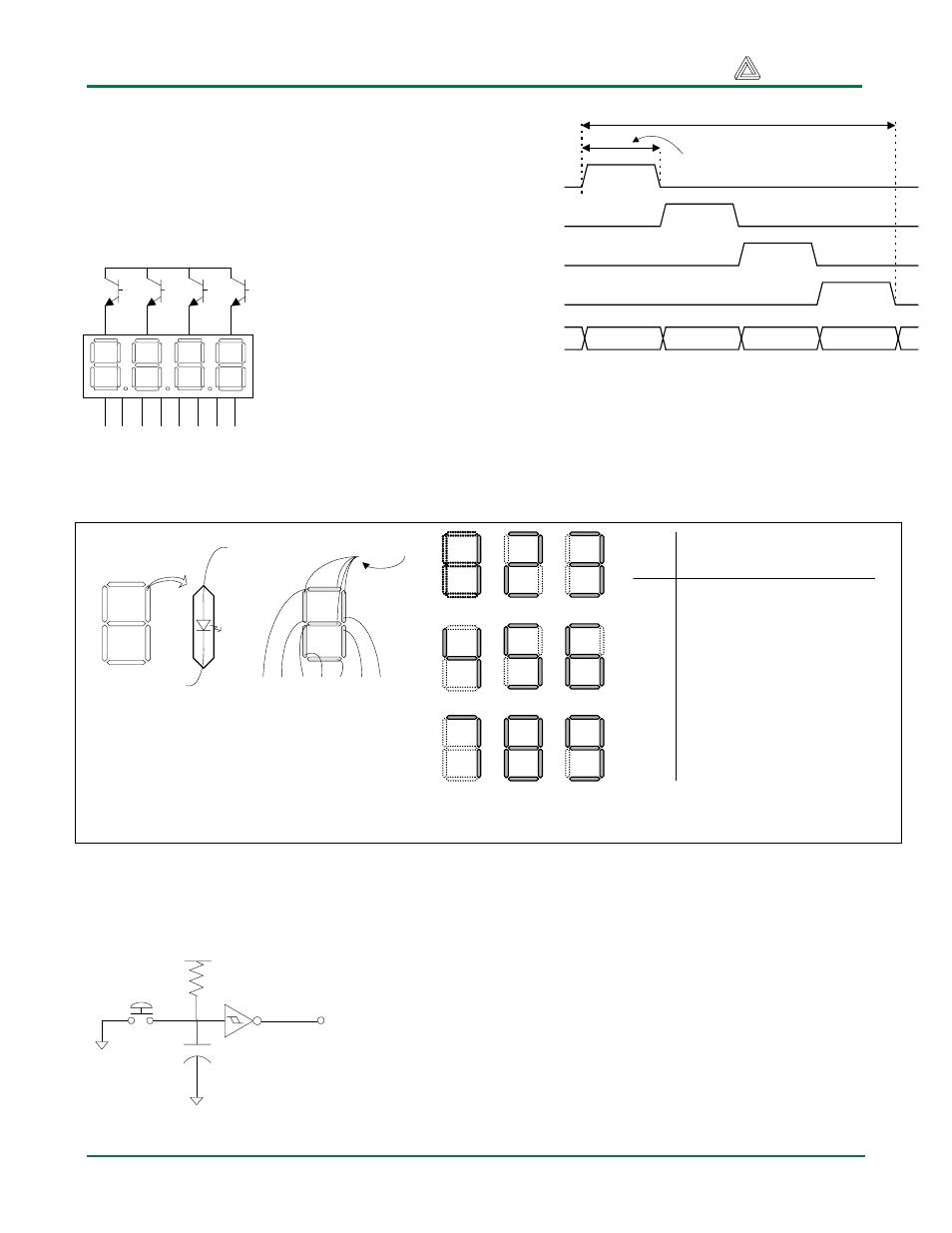
are driven for 4ms in an endless succession, the
display will show “17” in the first two digits.
An example timing diagram is provided to the
right.
.
Push Buttons
The 5 momentary-contact push buttons are
normally high when unused; this high signal is
translated to a low signal by a Schmitt Trigger.
When the button is actively pressed the signal
is driven low, which the Schmitt Trigger will
translate to a high signal. The buttons exhibit a
worst-case bounce time of about 1ms. A
74HC14 Hex Schmitt Trigger inverter provides
the debounce filtering and ESD protection. The
button outputs are brought out directly to pins
on interface connector B.
a1
Cathodes -- connected to
CPLD pins via 100
Ω resistor
Anodes -- connected to CPLD
via transistors for greater current
Vdd
a b c d e f g dp
a2
a3
a4
AN1
AN2
AN3
AN4
Cathodes
Digit 1
Digit 2
Digit 3
Digit 4
Refresh period = 1ms to 16ms
Digit period = Refresh / 4
Seven segment display refresh signals and timings
Figure 3. (a) Seven segment display detail.
(b) common anode display configuration. (c)
segement illumination patterns for decimal
digits. ( d) segment illumination truth table.
Common anode
a
f
e
d
c
b
g
a f g e d c b
(a)
(b)
(c)
Digit
Illuminated Segment
Show
n
a b c d e f g
0
1 1 1 1 1 1 0
1
0 1 1 0 0 0 0
2
1 1 0 1 1 0 1
3
1 1 1 1 0 0 1
4
0 1 1 0 0 1 1
5
1 0 1 1 0 1 1
6
1 0 1 1 1 1 1
7
1 1 1 0 0 0 0
8
1 1 1 1 1 1 1
9
1 1 1 1 0 1 1
(d)
GND
4.7KOhm
To Connector
.01uF
GND
VCC