Digilent DIO1 User Manual
Page 8
Digilent DIO1 Reference Manual
Digilent, Inc.
www.digilentinc.com
page 8 of 10
Copyright Digilent, Inc. All rights reserved. Other product and company names mentioned may be trademarks of their respective owners.
CRT-based VGA displays use amplitude
modulated, moving electron beams (or cathode
rays) to display information on a phosphor-
coated screen. LCD displays use an array of
switches that can impose a voltage across a
small amount of liquid crystal, thereby
changing light permittivity through the crystal
on a pixel-by-pixel basis. Although the
following description is limited to CRT
displays, LCD displays have evolved to use the
same signal timings as CRT displays (so the
“signals” discussion below pertains to both
CRTs and LCDs).
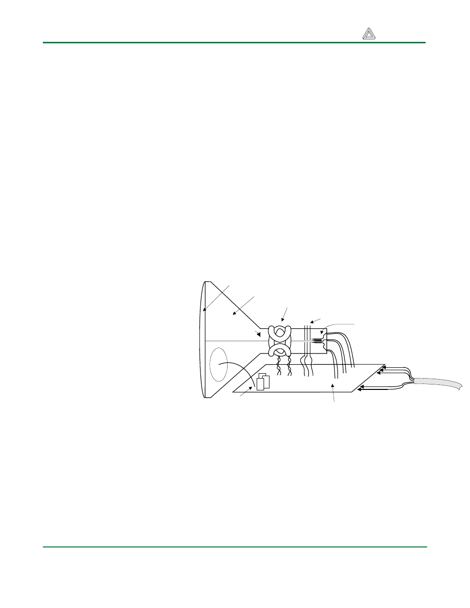
CRT displays use electron beams (one for red,
one for blue and one for green) to illuminate
phosphor that coats the inner side of the display
end of a cathode ray tube (see drawing below).
Electron beams emanate from “electron guns”,
which are a finely pointed, heated
cathodes placed in close proximity to
a positively charged annular plate
called a “grid”. The electrostatic force
imposed by the grid pulls away rays
of energized electrons as current
flows into the cathodes. These particle
rays are initially accelerated towards
the grid, but they soon fall under the
influence of the much larger
electrostatic force that results from
the entire phosphor coated display
surface of the CRT being charged to
20kV (or more). The rays are focused
to a fine beam as they pass through
the center of the grids, and then they
accelerate to impact on the phosphor
coated display surface. The phosphor surface
glows brightly at the impact point, and the
phosphor continues to glow for several hundred
microseconds after the beam is removed. The
larger the current fed into the cathode, the
brighter the phosphor will glow.
Between the grid and the display surface, the
beam passes through the neck of the CRT
where two coils of wire produce orthogonal
electromagnetic fields. Because cathode rays
are composed of charged particles (electrons),
they can be bent by these magnetic fields.
Current waveforms are passed through the coils
to produce magnetic fields that cause the
electron beams to transverse the display surface
in a “raster” pattern, horizontally from left to
right and vertically from top to bottom.
Information is only displayed when the beam is
moving in the “forward” direction (left to right
and top to bottom), and not during the time the
beam is reset back to the left or top edge of the
display. Much of the potential display time is
therefore lost in “blanking” periods when the
beam is reset and stabilized to begin a new
horizontal or vertical display pass.
The size of the beams, the frequency at which
the beam can be traced across the display, and
the frequency at which the electron beam can
be modulated determine the display resolution.
Modern VGA displays can accommodate
different resolutions, and a VGA controller
circuit dictates the resolution by producing
timing signals to control the raster patterns. The
controller must produce TTL-level
synchronizing pulses to set the frequency at
which current flows through the deflection
coils, and it must ensure that pixel (or video)
Cathode ray tube display system
Anode (entire screen)
High voltage supply
(>20kV)
Control board
Deflection coils
Grid
Electron guns
(Red, Blue, Green)
gun
control
grid
control
deflection
control
R,G,B signals (to guns)
Sync signals
(to deflection control)
Cathode ray tube
Cathode ray
VGA cable