Digilent 410-308P User Manual
Page 4
JTAG-SMT2-NC Reference Manual
Copyright Digilent, Inc. All rights reserved.
Other product and company names mentioned may be trademarks of their respective owners.
Page 4 of 14
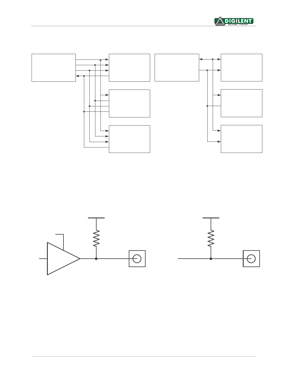
The IEEE 1149.7-2009 specification requires any device that functions as a debug and test system (DTS) to provide
a pull-up bias on the TMS and TDO pins. In order to meet this requirement, the JTAG-SMT2-NC features weak pull-
ups (100K ohm) on the TMS, TDI, TDO, and TCK signals. Though not required in the specifications, the pull-ups on
the TDI and TCK signals ensure that neither signal floats while another source is not driving them (see Fig. 5).
VREF
Output Pin
(TMS, TDI, TCK)
1
0
0
K
JtagEN
VREF
Input Pin
(TDO)
1
0
0
K
Users should place a current limiting resistor between the TMS pin of the SMT2-NC and the TMSC pin of the TS
when using the JTAG-SMT2-NC to interface with a 1149.7 compatible TS. If a drive conflict occurs, this resistor
should prevent damage to components by limiting the amount of current flowing between the pins of each device.
A 200 ohm resistor will limit the maximum current to 16.5mA when using a 3.3V reference (see Figs. 6 & 7). While
this level of resistance should be sufficient for most applications, the value of the resistor may need to be adjusted
to meet the requirements of the TS.
2-Wire Star Topology
TMSC
TDIC
TCKC
TDOC
Target
System 0
Target
System 1
Target
System N
TMSC
TDIC
TCKC
TDOC
TMSC
TDIC
TCKC
TDOC
TMS
TDI
TCK
TDO
Host
+
JTAG-SMT2-NC
(DTS)
TMSC
TDIC
TCKC
TDOC
Target
System 0
Target
System 1
Target
System N
4-Wire Star Topology
TMSC
TDIC
TCKC
TDOC
TMSC
TDIC
TCKC
TDOC
TMS
TDI
TCK
TDO
Host
+
JTAG-SMT2-NC
(DTS)
Figure 4. 4-Wire and 2-Wire star topology.
Figure 5. Pull-ups on TMS, TDI, TDO, and TCK signals.