Attaching the network and serial cables, Connecting the power and verifying installation – Comtrol 500 DeviceMaster User Manual
Page 14
14 - DeviceMaster 500 User Guide: 2000501 Rev. A
Hardware Installation
Hardware Installation
4.
Optionally, attach the light pipes. The following light pipes have been tested
and found to function; Bivar, Inc. (P/N:LP-230) and Ledtronics, Inc.
(P/N:LTP003-0CW-001).
After mounting the DeviceMaster 500, you are ready to connect the cables.
Attaching the
Network and Serial
Cables
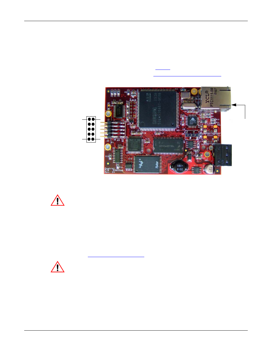
Use the following procedure to attach the serial ribbon and Ethernet cables. For a
larger illustration of the system, see
1.
Attach the ribbon cable built in
Building the Serial Ribbon Cable
to the header labeled J3.
2.
Connect a standard Ethernet cable from the RJ45 port on the DeviceMaster
500 to your Ethernet hub.
The default serial port setting on the DeviceMaster 500 is RS-232. Do
not connect the serial device until you have configured the serial port
settings. You must configure network settings and upload firmware
before configuring the serial port settings.
Use the next subsection to wire the power terminal connector and verify the
hardware installation.
Connecting the
Power and Verifying
Installation
Use the following procedure to wire the power terminal connector and connect the
DeviceMaster 500 to a power source.
1.
Connect the screw terminal power connector to the wires.
Locally-supplied power supplies must conform to the specifications provided in
Observe proper ESD techniques when connecting and disconnecting
the DeviceMaster 500.
2.
Use a small flat head screw driver to lock the wires into place.
Ethernet
10/100
Connector
J3
1
2
9
10
Caution
Caution