Mounting the embedded 1-port – Comtrol 500 DeviceMaster User Manual
Page 13
Hardware Installation
DeviceMaster 500 User Guide: 2000501 Rev. A - 13
Hardware Installation
Mounting the
Embedded 1-Port
Use the following procedure to mount the DeviceMaster 500 1-Port Embedded
with the 5-30VDC power supply.
Observe proper ESD techniques when handling the DeviceMaster 500.
1.
Carefully remove the DeviceMaster 500 from the anti-static bag, following
standard electrostatic device handling procedures.
Note: Write down the MAC address located on a label on the bottom (solder
side) center of the DeviceMaster 500 because you may need it during
configuration.
2.
Mount the DeviceMaster 500 for your environment using 1/4” stand-offs to
separate the DeviceMaster 500 from the base.
3.
Use one of the following methods to ground the DeviceMaster 500.
•
Through the power supply by connecting the ground wire on the power
cable using plastic or metal stand-offs.
•
Through the chassis, using metal stand-offs. If plastic stand-offs are used
to mount the board, then you must ground the DeviceMaster 500 using the
power cable.
Note: The maximum diameter of the metal stand-offs should be 0.175” with a
4-40 machine screw. Metal stand-offs are not provided with the
DeviceMaster 500.
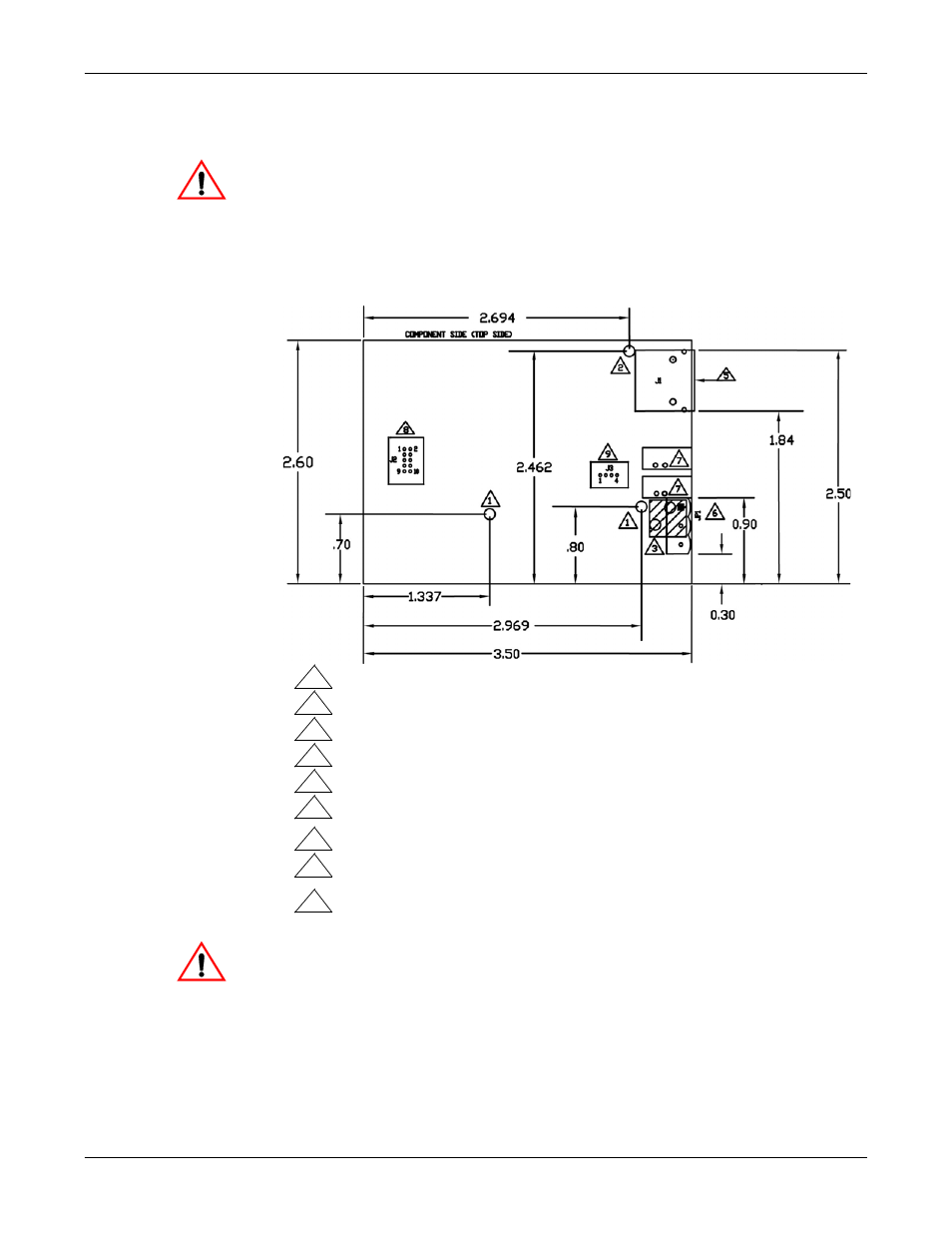
Caution
Non-plated/non-grounded mounting holes 0.116” diameter (+/-0.003”).
WARNING: Holes in hatched area are not mounting holes.
Maximum component height above board is 0.55”.
Ethernet connection J2: J2 overhangs board edge by 0.14” and the height is 0.55”.
LED light pipe mounting holes. The LED light pipes are not provided.
Serial port connector J3: 0.1” pin spacing, 0.025” square pin diameter, and 0.230”
pin height.
Debug port connector J4: 0.1” pin spacing, 0.025” square pin diameter, and 0.230”
Power connector; the mating connector is Weidmuller P/N: 152651.
1
3
4
5
6
7
8
9
Plated/chassis grounded mounting hole 0.116” diameter (+/-0.003”).
2
pin height.
5-30VDC Model
Caution