Comtrol PROFINET IO User Manual
Page 7
DeviceMaster UP PROFINET IO Installation Quick Start
2000484 Rev. E 7
Configuring Read/Write Devices
(see table below) in the output buffer. The length field is two bytes, and starts at the 2nd byte.
‐
Triggering the send. The data will not be sent through the serial port until the DeviceMaster UP sees that
the sequence number in the Output data is incremented. The DeviceMaster UP is informed of the new
sequence number during the next I/O cycle. So, with a cycle time of 32ms (specified in Step7 the
DeviceMaster UP will begin sending the data within 32ms. The data will be only sent once, and no further
data will be sent until the sequence number is again updated. This prevents the same data from being sent
over and over out the serial port.
‐
Verifying that the data has been sent. If you wish to confirm that the last data written to the output data
area has been sent out the serial port, check the input memory for the same output module. This 16‐bit
integer is the last data packet that was sent out the serial port. So, to confirm that the current packet has
been sent, compare the sequence number (a WORD) in the output data with the input data for that module.
In the screen shot (above), we would compare PIW 600 with QW 608. If they are the same, the data has been
sent.
•
Writing Out the Socket Port
‐
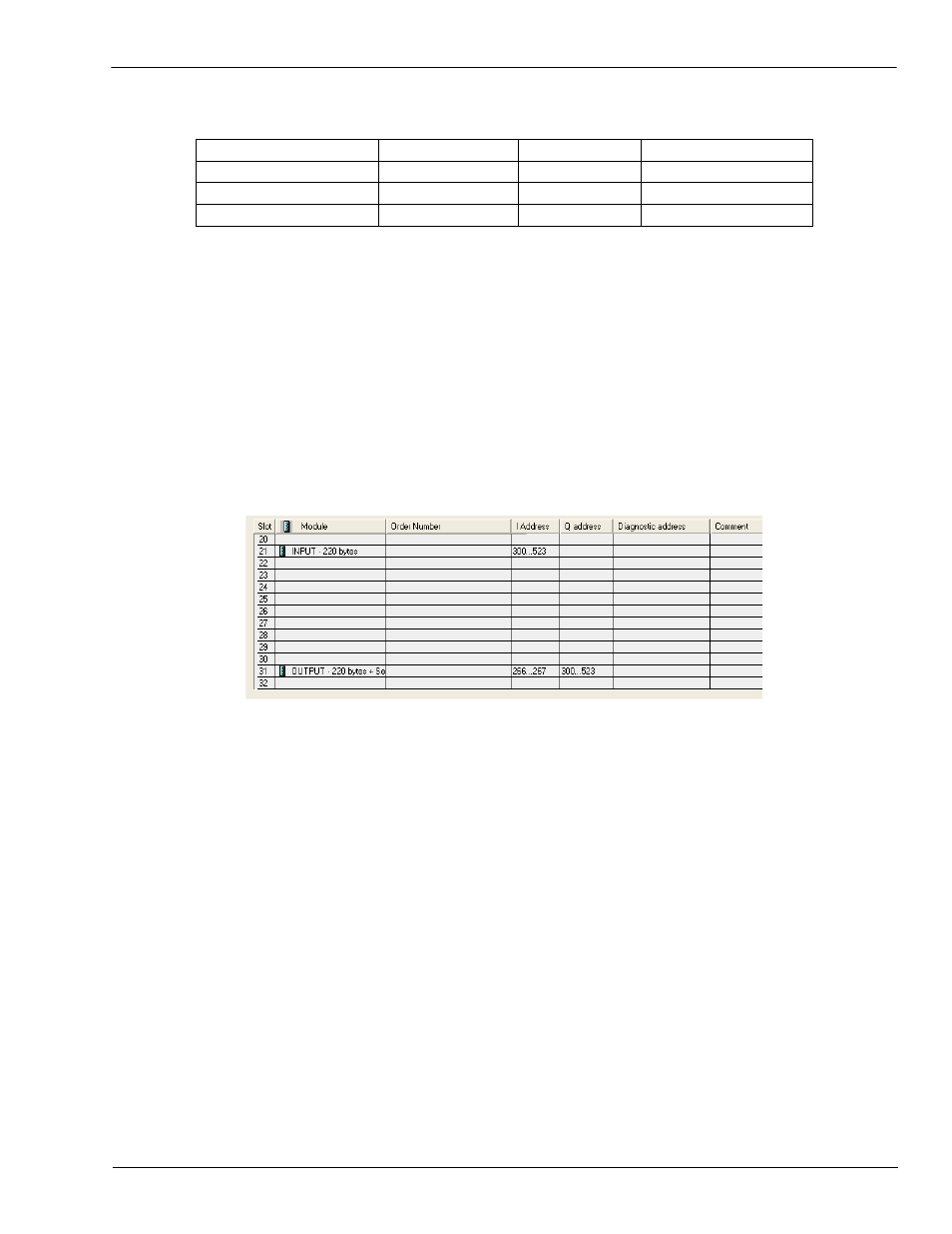
Use the correct slot. To write data out the socket port, place an Output module in Slot 31. Slot 31 is the
only slot that can be used to write Output data to the socket. The input and output modules for socket 1 are
shown below with 220 byte buffers.
‐
The remaining steps are exactly the same as those for writing out a serial port. Only the slot changes.
Field Name
Offset in BYTES
Data Type
Data Value(s)
Sequence number
0
WORD
0‐65536 (0xFFFF Hex)
Data length (in BYTES)
2
WORD
0‐220
Data
4
Array of BYTEs
User controlled