Configuring read/write devices – Comtrol PROFINET IO User Manual
Page 6
6 2000484 Rev. E
DeviceMaster UP PROFINET IO Installation Quick Start
Configuring Read/Write Devices
example, the first “packet” received from the DeviceMaster UP might have a sequence number of 1 (0x0001), a length of
7 bytes (0x0007) and seven data bytes (for instance ABCDEFG, or {0x41, 0x42, 0x43, 0x44, 0x45, 0x46, 0x47} in ASCII
text).
Note: If the buffer specified in Step7 is not large enough, the data is truncated and an error is logged.
The format of data sent is:
Configuring Read/Write Devices
The previous two sections explained how to receive serial or TCP/IP data on the PNIO controller through the
DeviceMaster UP. This section explains how to write data to the serial or TCP/IP device as well.
Follow the procedures in
Configuring ReadOnly Serial Devices
Configuring ReadOnly Ethernet TCP/IP
on Page 4 and use the following procedure to complete the procedure for read/write devices.
Note: Make sure that you have performed
1. Access the Server Configuration web page using one of the following methods:
•
Entering the IP address in your web browser
•
Right‐click the DeviceMaster UP in PortVision DX and click Web Manager
2. Open the embedded web page for the serial or socket port.
•
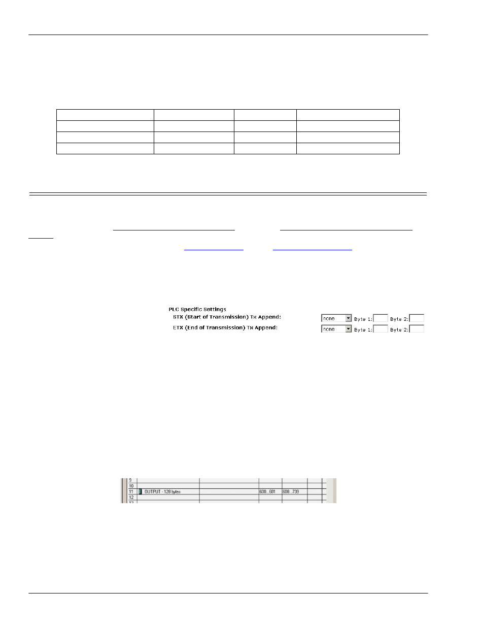
Serial ports: Set up the
transmit serial packet
identification.
‐
If desired, set the STX
(Start of transmission) Tx
Append
in decimal format for the PLC and/or the application. This will append the STX byte(s) to your
transmitted message. Refer to your serial device's User Manual for this setting.
‐
If desired, set the ETX (End of transmission) Tx Append in decimal format for the PLC and/or the
application. This will append the ETX byte(s) to your transmitted message. Refer to your serial device's User
Manual for this setting.
3. If any embedded web page settings have changed, verify Reset Port and Save in Flash are selected and click Submit.
4. Configure your controller to send data out the serial or socket ports.
Data Format: To send data from the PLC, simply write a packet to the OUTPUT memory configured in Step7. The
OUPUT
memory packets are in the same format as the incoming packets – both have 16‐bit sequence numbers and
lengths – only the direction of the data flow has changed. The following steps explain this in greater detail.
•
Writing Out the Serial Port
‐
Use the correct slot. To write data out the serial port, use the output module configured for Slot 11. Just as
Slot 1 is used for incoming serial data, Slot 11 is used for outgoing serial data.
‐
Fill in the data. Write the data into the output memory. The data that will be written out the serial port
starts 4 bytes into the memory buffer. You can write as much data as the memory buffer will hold.
‐
Controlling how much data is sent. Although the maximum amount of data sent is limited by the size of
the output module configured in Step7, the actual amount of data written is controlled by the length field
Field Name
Offset in BYTES
Data Type
Data Value(s)
Sequence number
0
WORD
0‐65536 (0xFFFF Hex)
Data length (in BYTES)
2
WORD
0‐220
Data
4
Array of BYTEs
User controlled