Technical support – Comtrol PROFINET IO User Manual
Page 18
18 2000484 Rev. E
DeviceMaster UP PROFINET IO Installation Quick Start
Technical Support
Technical Support
on Page 17 section before contacting Technical Support. If you need technical support,
contact Comtrol using one of the following methods.
Why can’t I see the incoming
data even though there are no
fault indications on the PLC?
Why are my Input Memory
addresses so high?
The DeviceMaster UP delivers relatively large amounts of data to the PLC (i.e. we are
not simply delivering 8 digital I/Os or a few analog values) Step7 frequently puts the
Input Data from our device outside the “Process Image”.
What is the Process Image?
The Process Image is a special area of memory that is always kept consistent. That
is, all the data in the buffer is from a single I/O cycle, and can not have part of a new
packet in it if new data arrives while the program is processing it. However, the PI is
also limited in size, and so large (e.g. 128 byte) buffers are often stored outside the
PI.
Reading Consistent Data From Outside The Process Image
In order to ensure that the data being processed in their logic is consistent (i.e. it is
all from a single serial packet) they should copy their data to a data block before
processing it. This is done using DPRD_DAT (SFC14), see the example on Page 10.
Siemens PLCs require a slightly different form of addressing the input data that is
not in the Process Image. Namely, instead of expressing the address as IW600
(input word at address 600) one must type PIW600 (pointer input word 600). This
is true for the Variable Table provided by Step7 to monitor memory on the PLC and
for some PLC instructions as well.
Writing Consistent Data Outside The Process Image
To write data consistently, use the DPWR_DAT (SFC15) to copy data from a DB
(data buffer) to the output memory, see
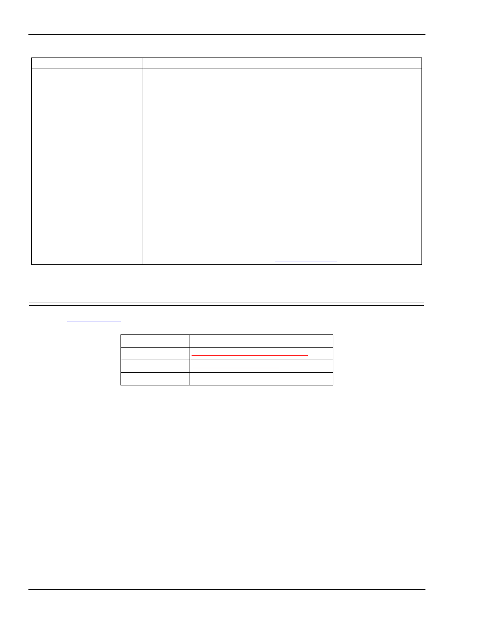
Contact Method
Corporate Headquarters
Downloads
Web site
Phone
(763) 957‐6000
Issue
Possible Corrective Action