Carrier EVERGREEN 19XR User Manual
Page 4
4
Step 5 — Connect Cable Between Display and
ICVC (International Chiller Visual Control)
1. Remove the knockout from the control panel box.
2. Pass the 25-ft coiled RS-485 cable, through the knock-
out. Approximately 16 to 20 in. of cable should be insert-
ed into the control box.
3. Connect one end of the RS-485 cable to the J8/SERVICE
port of the ICVC.
4. Connect the other end of the cable to the RJ14 connector
in the B&B Electronics converter provided with the dis-
play. The converter should then be attached to the 9-pin
serial port on the display. If chiller is connected to a CCN
network, see note below.
5. The ComfortVIEW™ software key is already installed in
the back side of the display. The software key will allow
preloaded software to run automatically when the display
screen is booted up.
6. After connecting both cable ends, connect the power cord
to the power brick and connect to the EverVu™ panel.
Pull the cord through the side of the back cover and attach
to the display.
7. If touch screen power cord was connected directly to the
chiller power panel rather than an AC outlet, remove
LOCK OUT and TAG OUT.
8. Turn on power to the display screen (lower right side) and
to the ICVC.
Before going to the job site to perform the installation, you
will need to know the chiller ICVC version. Some older ver-
sions need to be updated to work with the touch panel. Contact
a Carrier Service office for assistance in downloading a new
version, if required.
NOTE: Besides being connected to the display, the chiller
may be on a CCN network in the building. If this is the case,
make sure the correct wiring is utilized and coordinate with
the Carrier controls technician on the site. The refresh rate
of the touch screen display may need to be extended,
depending on the other devices on the network.
COMMUNICATION BUS WIRE SPECIFICATIONS —
The communication bus wiring is field-supplied and field-
installed. Bus wiring consists of shielded three-conductor cable
with drain (ground) wire. The cable selected must be identical
to the communication bus wire used for the entire network. See
Table 2 for recommended cable.
Table 2 — Recommended Cables
NOTE: Conductors and drain wire must be at least 20 AWG (Ameri-
can Wire Gage), stranded, and tinned copper. Individual conductors
must be insulated with PVC, PVC/nylon, vinyl, Teflon*, or polyethyl-
ene. An aluminum/polyester 100% foil shield and an outer jacket of
PVC, PVC/nylon, chrome vinyl or Teflon with aluminum operating
temperature range of –20 C to 60 C is required.
START-UP
Start Touch Screen System —
Once the ICVC and
display screen are powered up, the Touch Screen display will
boot up to a default graphical chiller for a Version 04XRV. The
CCN database for this display is defaulted to database only, so
there will be no communications.
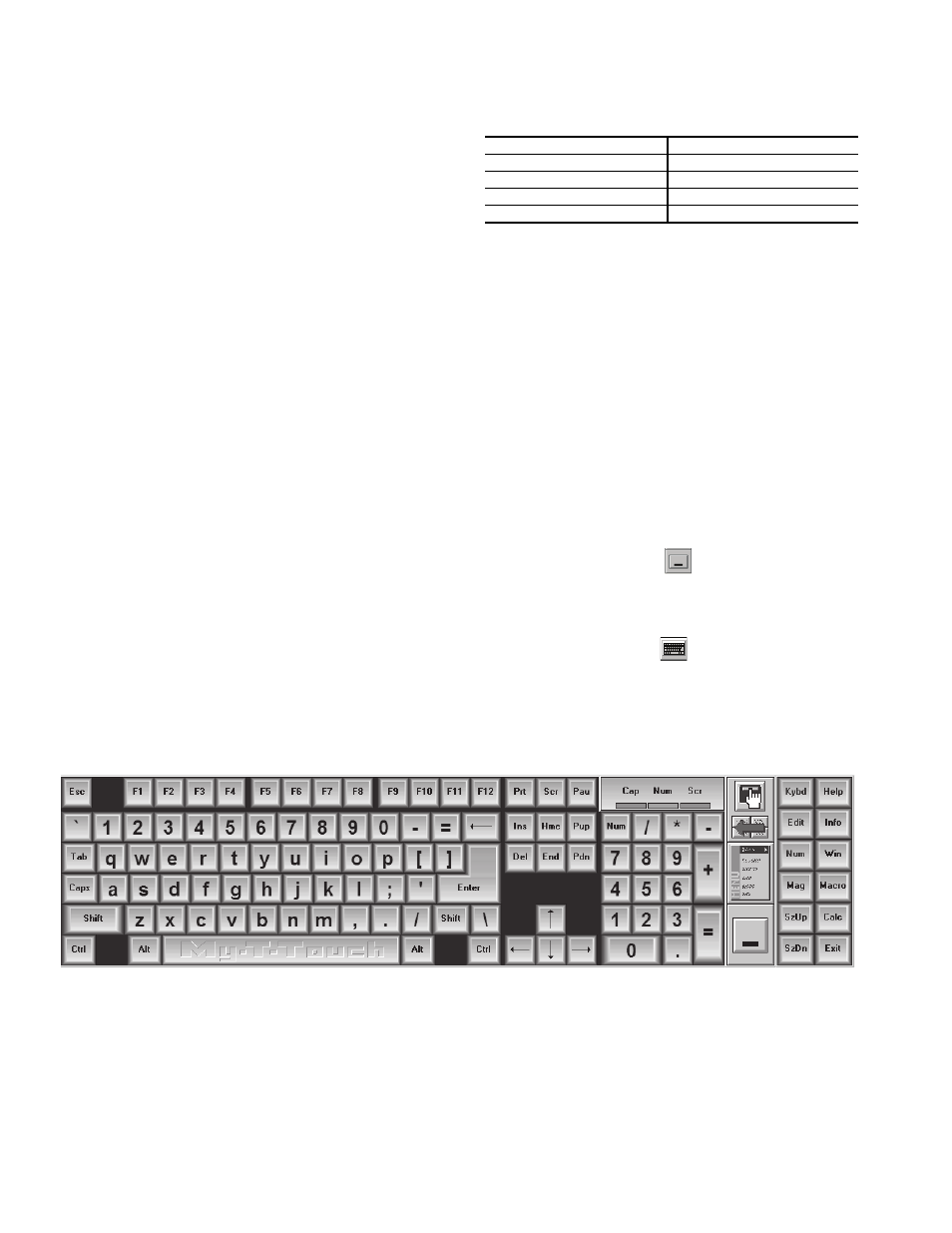
An expandable keyboard (Fig. 7) is viewable after boot up.
The keyboard is used for inputting data into any menu screen
or prompt that is the active.
The keyboard can be minimized to an icon again by press-
ing the large rectangular icon on the left side of the expandable
keyboard.
The keyboard can be viewed at any time by pressing the
keyboard icon at the top right side of any active screen or
prompt.
The expandable keyboard can be moved to different posi-
tions on the screen be touching any of the blue areas between
the keys and moving it to desired position on screen.
MANUFACTURER
CABLE PART NO
Alpha
2413 or 5463
American
A22503
Beiden
8772
Columbia
02525
Fig. 7 — Expandable Keyboard
a19-1898
*Registered trademark of DuPont.