Carrier EVERGREEN 19XR User Manual
Page 2
2
If the chiller software is an earlier version than is supported
by the EverVu display, the chiller software will need to be up-
graded to match the version of EverVu database that will be
cloned during the installation of the display.
If the chiller software is a later version than is supported by
the EverVu display, a new EverVu database will need to be
downloaded and imported into the EverVu display. Contact a
Carrier Service office for assistance in importing the databases.
INSTALLATION
Equipment Needed
•
3
/
16
in. hex screwdriver
•
1
/
4
-20-1 in. hex bolts
• Voltmeter
Step 1 — Identify Power Supply
POWER REQUIREMENTS — The EverVu™ panel is pro-
vided with a 25-ft Beldon power cable and plug for connection
to a 120-v receptacle. If 120-v receptacle is available, proceed
to Step 2. If 120-v receptacle is not available, power may be
obtained directly from the chiller power panel by following the
instruction below.
Connecting Power Cable to Chiller Power Panel — The
following instructions are for connecting the power cable of the
display panel directly to the 110-v supply at the chiller power
panel. If the power cable of the display can be connected to a
120-v receptacle, this step is not necessary; proceed to Step 2.
1. Identify the oil heater contactor (1C) in the chiller power
panel.
2. Using a voltmeter, check the voltage across Terminals
22 and 23. The voltage should be 110 v
10%. If the
voltage is not within this range, STOP immediately
and consult an appropriate electrical specialist.
3. Using a voltmeter, verify that Terminal 23 in oil heater
contractor is neutral. If not, STOP immediately and
consult an appropriate electrical specialist.
4. After verifying voltages in Steps 2 and 3, turn off
chiller power and verify that the oil heater contractor is
deenergized and no voltage is present at the input
Terminals 22 and 23.
5. LOCK OUT and TAG OUT power supply to the chill-
er power panel.
6. Remove the plug of the display panel power cord with a
wire cutter.
7. Strip approximately 6 in. of insulation off power cable
end.
8. Using two fork connectors (red and blue), crimp accord-
ing to the following color code:
a. WHITE wire to RED connector
b. BLACK wire to BLUE connector.
9. Strip the insulation off the green grounding wire.
10. Remove the electrical knockout from the panel and
add a strain relief connection, if necessary.
11. Pulls the wires through strain relief and connect the
green grounding wire to the grounding lug. Connect
the fork terminals to the input of the oil heater circuit
breaker as follows:
a. 1C-22 to RED fork terminal (WHITE wire)
b. 1C-23 to BLUE fork terminal (BLACK wire).
12. For safety reasons, do not remove LOCK OUT and TAG
OUT until completing Step 5 — Connect Cable Between
Display and ICVC (International Chiller Visual Control).
Step 2 — Assemble Swing Arm —
Refer to sepa-
rate Swing Arm Assembly Instructions provided in package.
Step 3 — Attach Arm to Tube Sheet
1. Identify the tube sheet on the evaporator (19XR,XRV) or
condenser (23XRV) where the display is to be mounted.
Insert the bolt into the center hole of the tube sheet
mounting bracket.
NOTE: Do not remove the white plastic piece inside
the mounting bracket. This serves to insulate the metal
between the tube sheet and mounting bracket.
2. Attach the
1
/
4
-20-1 in. hex bolts halfway through in the
base of the mounting bracket. Do not tighten com-
pletely.
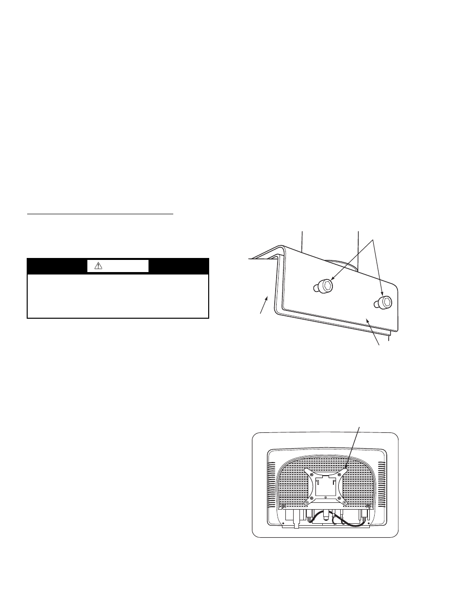
3. Align the arm mounting bracket to the tube sheet and
tighten hex bolts using a
3
/
16
hex screwdriver. See Fig. 1.
Step 4 — Mount Display Screen on Arm
Mounting Bracket —
Locate the EverVu display panel.
Do not remove the plastic covering until you are ready to start
up the touch screen. The display screen is shipped with the
quick connect mount attached to the back of the screen. See
Fig. 2.
WARNING
Electrical shock can cause personal injury and death. Shut
off all power to this equipment during installation. There
may be more than one disconnect switch. Tag all discon-
nect locations to alert others not to restore power until work
is completed.
Fig. 1 — Attach Arm to Tube Sheet
MOUNTING
BOLTS
TUBE
SHEET
ARM BASE
a19-1891
Fig. 2 — Display Panel with Mount Attached
BACK OF DISPLAY PANEL
DISPLAY MOUNT
a19-1890