11 sata interface (option), Sata interface (option), Digital-logic ag – Compaq SmartCore Express SMA200 User Manual
Page 35
DIGITAL-LOGIC AG
SMA200 Manual V1.0
35
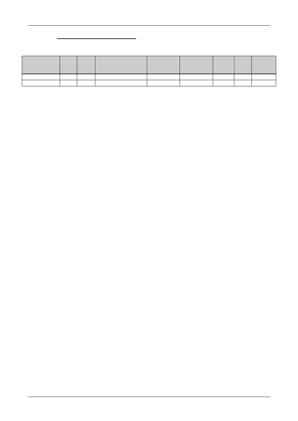
5.4.11. SATA Interface (Option)
Signal
BUS
Type
Description
On Module
Termination
Ext. Ter-
mination
Needed
Max.
Length
in mm
Ohm
Matched
Length
in mm
SATA_Tx[0..3] SATA
Dif
SATA transmitter pair
Series 10nF
100
100
-
SATA_Rx[0..3] SATA
Dif
SATA receiver pair
Series 10nF
100
100
-
If the signals are not used:
Unused SATA interfaces may be open.
Remarks:
The 10nF capacitors 0402 need to be placed directly at the SATA connector.
Maximum via count is 2 per signal.
BUS to BUS spacing is min. 20mil = 0.5mm
Pair to Pair spacing is min.
35mil = 0.9mm
The SATA_LED# output show the SATA (all ports) activity. The LED must be connected to +3.3V with
a series resistor of 330 Ohm to the “SATA_LED#” signal.
EMV/EMI filters:
Are not needed.
- Netelligent 8500 (3 pages)
- 127453-B21 (4 pages)
- AlphaPC 164LX (82 pages)
- QUICKSPECS 294162-B21 (1 page)
- PowerLeap JP2 (6 pages)
- 5900 (1 page)
- 517212-001 (26 pages)
- 212953-B21 (2 pages)
- NC3132 (4 pages)
- 705 (2 pages)
- au-Series (11 pages)
- AlphaPC 164SX (72 pages)
- 21264 (356 pages)
- PROLIANT 3000 (137 pages)
- ProLiant p-Class (24 pages)
- TL895 (10 pages)
- Microcom 420 (2 pages)
- uSign Signature Capture Module uSign 200 (18 pages)
- Universal Notebook Power Adapter SPS-2406 (4 pages)
- RAID ARRAY 3000 EK-SMCPO-UG. C01 (112 pages)
- DA-10121 (3 pages)
- AlphaStation XP1000 (16 pages)
- MICROSPACE MSEBX800 (53 pages)
- Contec RS-232C (77 pages)
- SDLT 220GB (8 pages)
- Cabinet H9A11 (32 pages)
- MTEK6000 (81 pages)
- SANetworks Network View DA10682 (6 pages)
- AA-RHGWB-TE (320 pages)
- OXYGEN VX1 (29 pages)
- COM Express Extension (24 pages)
- Lithium-ion battery (7 pages)
- 164SX (72 pages)
- 3200 (211 pages)
- AA-Q88CE-TE (320 pages)
- MSB900L (66 pages)
- WL100 (2 pages)
- Wireless LAN 100 (2 pages)
- 1000 LX (4 pages)
- AAR-88LB-TE (42 pages)
- PC100 (66 pages)
- VAX 7000 Model 810 (9 pages)
- 99875320-5 (44 pages)
- CP-2E (91 pages)