5 parallel ata, Parallel ata, Digital-logic ag – Compaq SmartCore Express SMA200 User Manual
Page 29
DIGITAL-LOGIC AG
SMA200 Manual V1.0
29
5.4.5.
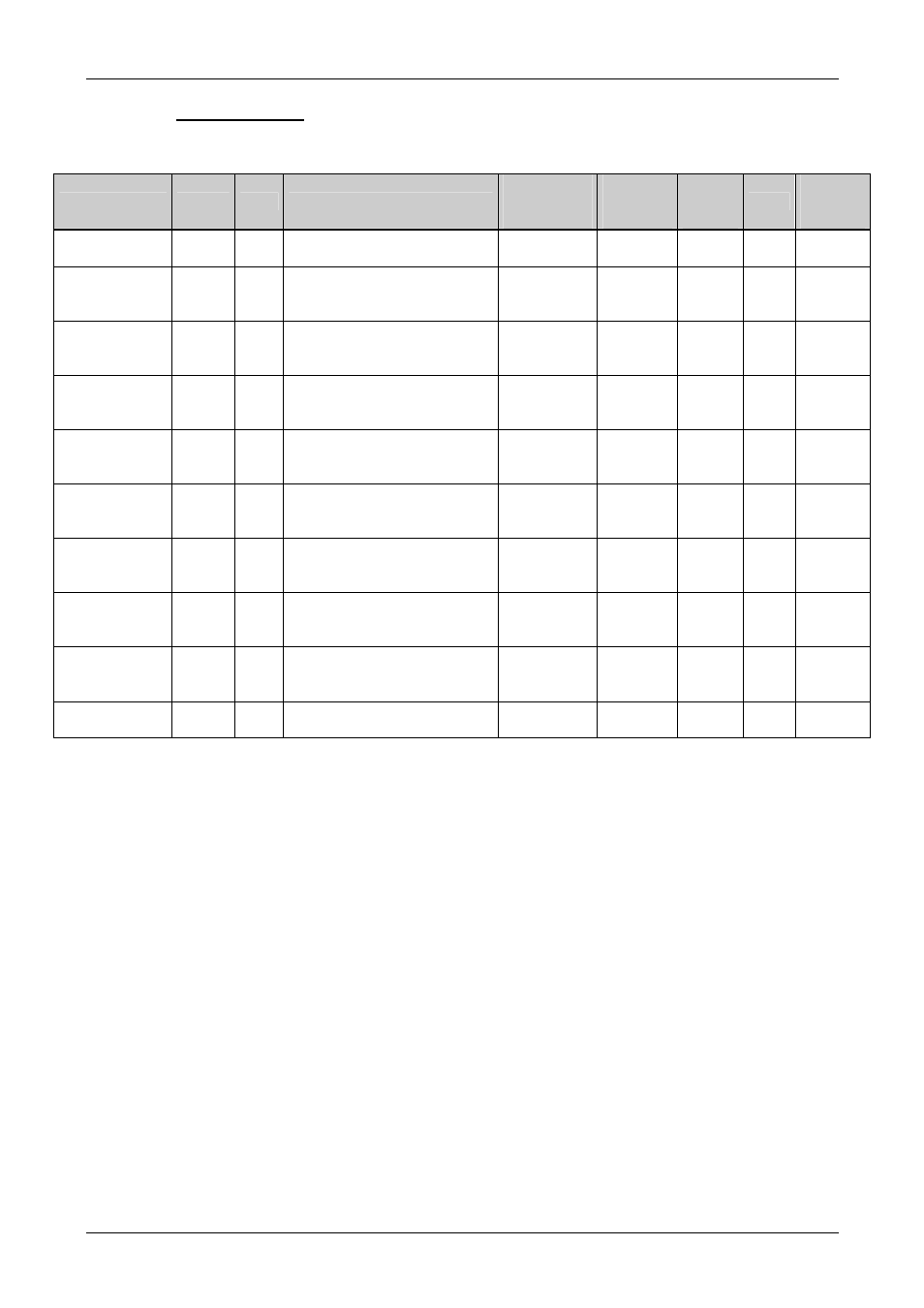
Parallel ATA
Signal
BUS
Type Description
On Module
Terminatio
n
Ext. Ter-
mination
Needed
Max.
Length
in mm
Ohm
Matched
Length
in mm
PATA_D[15..0] CMOS
5V
I/O
IDE data signals
Series 33
-
100
55
-
PATA_A[0..2]
CMOS
5V
Out
IDE address signal.
Connect directly to the PATA
device.
-
-
100
55
PATA_IOR#]
CMOS
5V
Out
IDE control signal.
Connect directly to the
PATA-device.
-
-
100
55
PATA_IOW#]
CMOS
5V
Out
IDE control signal.
Connect directly to the
PATA-device.
-
-
100
55
PATA_DACK#] CMOS
5V
Out
IDE control signal.
Connect directly to the
PATA-device.
-
-
100
55
PATA_CS[3,1] CMOS
5V
Out
IDE control signal.
Connect directly to the
PATA-device.
-
-
100
55
PATA_REQ
CMOS
3/5V
In
IDE control signal.
Connect directly to the
PATA-device.
-
-
100
55
PATA_IORDY
CMOS
3V
In
IDE control signal.
Connect directly to the
PATA-device.
PU 4.7k to
3.3V
-
100
55
PATA_IRQ
CMOS
3V
In
IDE control signal.
Connect directly to the
PATA-device.
PU 10k to
3.3V
-
100
55
PATA_PCSEL CMOS
3V
In
GND = SSD works as master
HIGH = SSD works as slave
PD 4.7k to
GND
100
55
If the signals are not used:
All this PATA signals may be left open.
Remarks:
EMV/EMI filters:
Are not needed.