2 sdvo, Sdvo, Digital-logic ag – Compaq SmartCore Express SMA200 User Manual
Page 26
DIGITAL-LOGIC AG
SMA200 Manual V1.0
26
5.4.2.
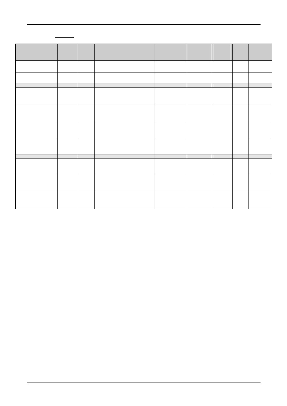
SDVO
Signal
BUS
Type
Description
On Module
Termination
Ext. Ter-
mination
Needed
Max.
Length
in mm
Ohm
Matched
Length
in mm
SDVO_CTRLCLK SDVO
DDC signal
PU 4.7k to
3.3V
55
SDVO_CTRLDAT SDVO
DDC signal
PU 4.7K to
3.3V
55
SDVO_CLK +/-
SDVO
Dif
Out
Needs a series 100nF
capacitor to connect to an
SDVO converter chip
-
-
100
100
0.5
SDVO_INIT +/-
SDVO
Dif
In
Needs a series 100nF
capacitor to connect to an
SDVO converter chip
-
-
100
100
0.5
SDVO_STALL +/- SDVO
Dif
In
Needs a series 100nF
capacitor to connect to an
SDVO converter chip
-
-
100
100
0.5
SDVO_TVCLKIN +/-
SDVO
Dif
In
Needs a series 100nF
capacitor to connect to an
SDVO converter chip
-
-
100
100
0.5
SDVO_Red +/-
SDVO
Dif
Out
Needs a series 100nF
capacitor to connect to an
SDVO converter chip
-
-
100
100
0.5
SDVO_Green +/- SDVO
Dif
Out
Needs a series 100nF
capacitor to connect to an
SDVO converter chip
-
-
100
100
0.5
SDVO_Blue +/-
SDVO
Dif
Out
Needs a series 100nF
capacitor to connect to an
SDVO converter chip
-
-
100
100
0.5
If the signals are not used:
All these SDVO signals may be left open.
Remarks:
For the DDC signals, a voltage translator to 3.3V or 5V is needed.
Pair to Pair spacing:
35mil = 0.9mm
Pair to Pair matching:
better than 25mm
BUS to BUS spacing:
20mil = 0.5mm
The AC coupling capacitors (100nF / 0402) must be placed near the device for the Tx signals only.
The maximum number of vias per signal is less than 4.
Supported devices:
SiliConImage SIL1362 / SIL1364 (DVI)
Chrontel CH7021 (SDTV / HDTV / CRT)
EMV/EMI filters:
Chokes are needed.