4 smartcoreexpress signal groups, 1 pci-express, Smartcoreexpress signal groups – Compaq SmartCore Express SMA200 User Manual
Page 25: Pci-express, Digital-logic ag
DIGITAL-LOGIC AG
SMA200 Manual V1.0
25
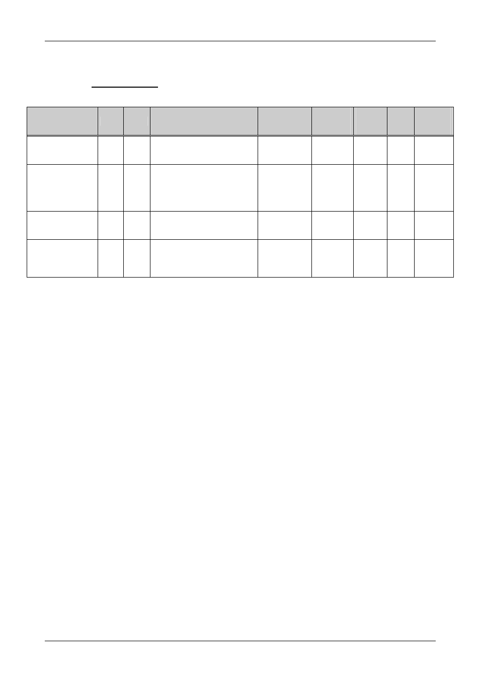
5.4. smartCoreExpress Signal Groups
5.4.1.
PCI-Express
Signal
BUS Type Description
On Module
Termination
Ext. Ter-
mination
Needed
Max.
Length
in mm
Ohm
Matched
Length
in mm
PCIe_Tx [0-4] +/- PCIe
Dif
Out
Transmitter 2.5Gbit
Connected to an Rx pin pair
of the device.
100nF Series
Cap.
-
200
100
0.2
PCIe_Rx [0..4] +/-
PCIe
Dif
In
Receiver 2.5Gbit
Connected to a Tx pin pair
of the device. The Tx output
of the device needs an AC
coupling capacitor.
-
Series
Cap.
100nF
As 0402
200
100
0.2
PCIe_CLK[0..4] +/-
PCIe
Dif
Out
Reference clock (100MHz)
Connected to a Refclock pin
pair of the device.
-
-
200
100
0.2
PCIe_REQ#[0..4] PCIe
3.3V
In
A low signal at this input will
enable the PCI-Clk-Output
of the corresponding PCI-
Express lane.
PU
integrated in
the CK540
-
200
Static
-
If the signals are not used:
All these PCI-Express signals may be left open.
Remarks:
Pair to Pair spacing:
35mil = 0.9mm
BUS to BUS spacing:
20mil = 0.5mm
The AC coupling capacitors must be placed near the device for the Tx signals only. The maximum
number of vias per signal is less than 4.
EMV/EMI filters:
Are not needed.