Smartcoreexpress pcb pad design, Digital-logic ag – Compaq SmartCore Express SMA200 User Manual
Page 17
DIGITAL-LOGIC AG
SMA200 Manual V1.0
17
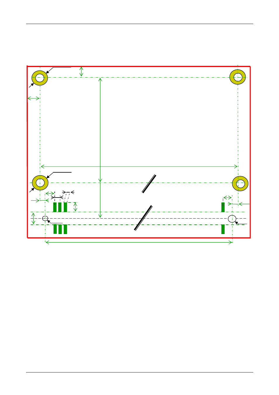
3.3. Connector Placement & Pin Definition on the Carrier
Board
View of the Top Side (mounting side) of the smartCoreExpress PCB:
d=2.2/D=4.5
3.6mm
A1 A2 A3 ...
B1
A110
B110
0.5
0.3
1.8
1.6
0.4
d=1.0
d=1.6
58.5mm
57.7mm
1.6
d=2.2/D=4.5
44.0mm
50.2mm
3.25
3.25
smartCoreExpress
PCB pad design
See also other documents in the category Compaq Hardware:
- Netelligent 8500 (3 pages)
- 127453-B21 (4 pages)
- AlphaPC 164LX (82 pages)
- QUICKSPECS 294162-B21 (1 page)
- PowerLeap JP2 (6 pages)
- 5900 (1 page)
- 517212-001 (26 pages)
- 212953-B21 (2 pages)
- NC3132 (4 pages)
- 705 (2 pages)
- au-Series (11 pages)
- AlphaPC 164SX (72 pages)
- 21264 (356 pages)
- PROLIANT 3000 (137 pages)
- ProLiant p-Class (24 pages)
- TL895 (10 pages)
- Microcom 420 (2 pages)
- uSign Signature Capture Module uSign 200 (18 pages)
- Universal Notebook Power Adapter SPS-2406 (4 pages)
- RAID ARRAY 3000 EK-SMCPO-UG. C01 (112 pages)
- DA-10121 (3 pages)
- AlphaStation XP1000 (16 pages)
- MICROSPACE MSEBX800 (53 pages)
- Contec RS-232C (77 pages)
- SDLT 220GB (8 pages)
- Cabinet H9A11 (32 pages)
- MTEK6000 (81 pages)
- SANetworks Network View DA10682 (6 pages)
- AA-RHGWB-TE (320 pages)
- OXYGEN VX1 (29 pages)
- COM Express Extension (24 pages)
- Lithium-ion battery (7 pages)
- 164SX (72 pages)
- 3200 (211 pages)
- AA-Q88CE-TE (320 pages)
- MSB900L (66 pages)
- WL100 (2 pages)
- Wireless LAN 100 (2 pages)
- 1000 LX (4 pages)
- AAR-88LB-TE (42 pages)
- PC100 (66 pages)
- VAX 7000 Model 810 (9 pages)
- 99875320-5 (44 pages)
- CP-2E (91 pages)