Liveling the ramge, Ш«?дш!!е the a.ht!-t» devics, When – GE 49-8338 User Manual
Page 41
Attention! The text in this document has been recognized automatically. To view the original document, you can use the "Original mode".
(continued)
Ш
liVELING THE RAMGE
1. Remove the storage
drawer, broiler drawer or
kick panel.
О T Тол <1 Q /1 a" ЛГ\Л«Л_£кП/^ r\V»
Ч-/ОЧ-.
<Л \J/
XV/ V/|/t^lX~dlU. V/1
socket wrench to back out
both rear leveling legs
approximately two turns.
3. Use a 1%" open-end or
adjustable wrench to back
out the front leveling legs
two turns.
4. Install the oven shelves in
the oven and position the range
where it will be installed.
5. Check for leyelness by placing a spirit level or
a cup, partially filled witii water, on one of the
oven racks. If using a spirit level, take two
r p n H i n c T Q — I f i v f i l nlar*p»H rliafmrtiilliT-ftrci-
^ V - « . w » * J.1..JLJ. W J L X * 4 L « * ^ X Z A X « * X A j r J.AX WU
in one direction and then the other.
6. Adjust the leveling legs until the range is level
7. After the range is level, slide the range away
from the wall so tliat the Anti-Tip device can be
installed.
'
JL
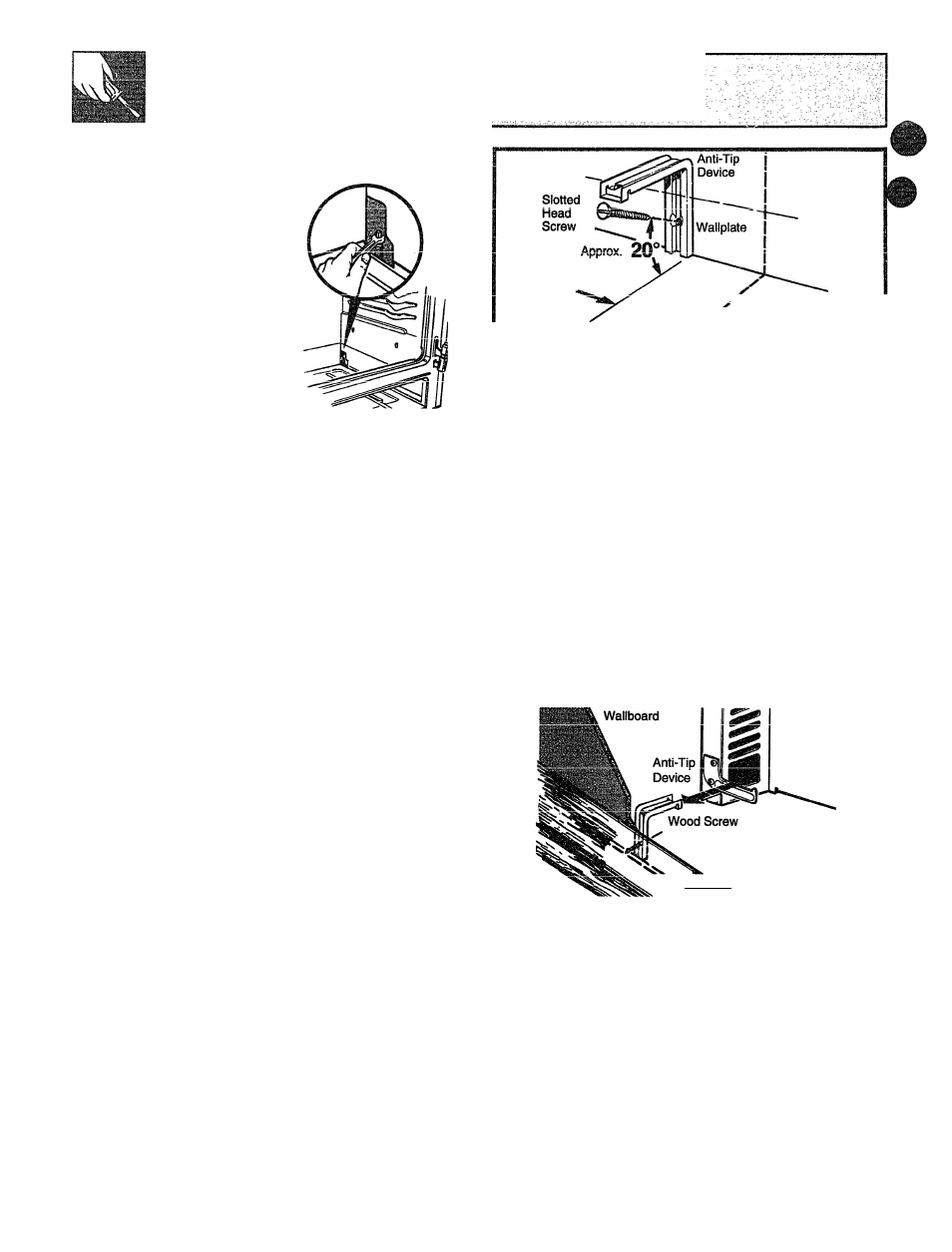
Ш«?ДШ!!е THE A.HT!-T» DEViCS
WARNING:
® Range must be secured with an approved
Anti-Tip device.
» Unless properly installed, the range could
be tipped by you or a child standing, sitting
leaning
ЛП on ЛГЛЛП Ar\f\^
\JIX CU
l
I
vxv
/
v
/
x
«
® After installing the Anti-Tip device, verify
that it is in place by carefully attempting to
tilt the range forward.
® This range has been designed to meet all
recognized industry tip standards for all
normal conditions.
® The use of this device does not preclude
tipping of the range when not properly
installed.
® K the Anti-Tip device supplied with the
range does not fit this application, use the
universal Anti-Tip device WB02X7909.
1. Mark the wall where the RIGHT EDGE of the
range is to be located. Be sure to allow for the
countertop overhang if you intend to install the
range next to cabinets.
40
2%''
Marked Edge
of Range
X
2. Locate the outside edge of the device
WTTfUVA tO.XV'
\JX UIXV/ X CIXX^V* XX V/XXX VXIV^ XIXCXIXVV^VX
edge of the range.
3s Usjng the device as a template, mark the.
position of the hole for the screw.
4. For wood construction, drill a pilot hole at an
angle of 20 degrees from the horizontal. A nail
or awl may be used if a drill is not available.
Mount the Anti-Tip device witii the screw
provided.
For cement or concrete construction, you
will need a 1/4" x
IW'
lag bolt and a 1/2" O.D.
sleeve anchor, which not provided. Drill
the recommended size hole for the hardware.
Install the sleeve anchor into the drilled hole
and then install the lag bolt through the device.
The bolts must be properly tightened as
recommended for the hardware.
Back of
пЗПув
Wallplate^^
5.
Slide the range against the wall, and check
for proper installation by grasping the front
edges of the rear surface unit openings and
~
4-1_____ X______ 1
i..aicxuuy aitciupuiijg tu uiL uic l iuigc xui Wciru.
WHEN
Ul
HOOKUK ME COMPIETED:
MUU SURE AU OOHTMU MB LEFT M THE
MiSe BMIteeWi№B8
MAKE SURE THE FLOW OF COMBUSTION ANB
УЕЙЛШЮЙ MR Ю THE RAN6E IS UHOBSTtUCTEB.
Г