Carrier AQUAZONE 50VS User Manual
Page 9
9
The direct return system shows the most common piping ar-
rangement. This is the most cost effective method of piping to
install since the water is supplied and returned to a riser column
at the same place, at the bottom or top of the building. Howev-
er, this type of system requires more effort to individually bal-
ance water flow to the units. The risers are normally capped at
the ends opposite the main supply and return piping and may
require a field-installed flush and vent loop.
The first reverse return system shows a system, which is
commonly used to minimize individual unit water flow balanc-
ing and is often referred to as “self balancing.” This riser ar-
rangement has a natural affinity to balance the flow to each unit
in the riser column. However, individual unit balancing may
still be required. This piping system is used on 2-pipe systems
only and has an individual return for each riser column.
The second reverse return system shows a system with a
common reverse return riser installed separately from the
individual unit riser columns. This riser arrangement allows for
more flexibility in individual unit riser sizing but has the same
general characteristics as the “reverse return” system described
above. It may also be a better fit for the particular structural and
architectural requirements of the building. This piping system
may also be used on 4-pipe systems.
Regardless of the system selected, optimum performance
can only be achieved through adjustment to the recommended
water flow at each individual unit (see Table 1 for individual
unit water flow requirements).
RISER MATERIAL, SIZING, AND INSULATION —
Some of the factors affecting riser application and sizing are
noise, tube erosion and economics. Water source heat pumps
maybe supplied with factory-installed risers; the riser material,
diameter, length and insulation thickness must be determined
for each unit based on its positioning within the building.
Figure 8 displays riser tube diameter sizes as a function of flow
(gpm), friction loss and water velocity. For maximum riser
velocity on pressure drop per 100 ft, refer to ASHRAE (Amer-
ican Society of Heating, Refrigeration, and Air Conditioning
Engineers) Fundamentals Handbook for Riser Sizing. Gener-
ally, riser copper type, size, length and insulation thickness are
determined by the location of the water source heat pump unit
in the building. Chilled water and hot water risers are available
in Type-M, Type-L copper, varying diameters from
3
/
4
to
2
1
/
2
in., and with either no insulation,
1
/
2
or
3
/
4
in. thick closed
cell foam insulation. Condensate risers are available in Type-M
copper, varying diameters from
3
/
4
to 1
1
/
4
in., and with no
insulation,
1
/
2
or
3
/
4
in. thick closed cell foam insulation. All
factory-supplied risers and riser extensions are insulated for the
full length of the riser, eliminating the need for field insulation.
Insulation is not required on loop water piping except where
the piping runs through unheated areas, outside the building or
when the loop water temperature is below the minimum
expected dew point of the pipe ambient conditions. Insulation
is required if loop water temperature drops below the dew
point (insulation is required for the ground loop applications in
most climates).
Riser sizing is generally based on the water flow require-
ments of each unit and the units on higher and lower floors that
tie into the same riser column depending on the piping system
chosen. Water piping is often designed at approximately 5 ft/s.
Keeping this in mind, risers can be reduced in size as the water
flow decreases from floor to floor. For low-rise buildings, riser
sizes can be of a single diameter.
The reduced material handling on site will often offset the
extra costs associated with the larger risers.
RISER EXPANSION — Generally, in medium to high-rise
buildings, allowances must be made for pipe expansion. In ap-
plications supplemented with factory (or field) supplied be-
tween the floor riser extensions, assemble and install exten-
sions before installing cabinet.
NOTE: Riser assemblies are designed to accommodate a
maximum of 1
1
/
8
in. expansion and contraction up to a total
movement of 2
1
/
4
inches. If the total calculated rise expansion
exceeds 2
1
/
4
in., expansion devices must be used (field
provided).
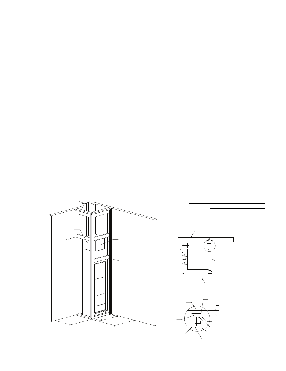
4-in. MIN
TOP VIEW
EXISTING WALL
RISERS
DRYWALL
RETURN PANEL
SUPPLY
RETURN
DRAIN
A
A
B
C
D
88.5 in.
SUPPLY OPENING
TO ABOVE FLOOR
SUPPLY
OPENING
DETAIL A
DRYWALL
EXISTING WALL
RETURN PANEL
FASTENERS BY OTHERS
FRAME
STUD
UNIT CABINET
GASKET
1 11/16 in. MIN
Fig. 6 — Framing Rough-In Detail
50VS UNIT
SIZE
DIMENSIONS (in.)
A
B
C
D
50VSA-VSH
24
5
/
8
30
11
/
16
24
5
/
8
63
11
/
16
50VSI-VSN
30
7
/
8
36
11
/
16
30
5
/
8
64
7
/
16
a50-8331.eps