Carrier AQUAZONE 50VS User Manual
Page 22
Manufacturer reserves the right to discontinue, or change at any time, specifications or designs without notice and without incurring obligations.
Catalog No. 04-53500046-01
Printed in U.S.A.
Form 50VS-1SI
Pg 22
311 11-08
Replaces: New
Copyright 2008 Carrier Corporation
has reached acceptable levels, the unit microprocessor will
power on automatically and resume previous operation.
LEAVING WATER TEMPERATURE SENSOR FAIL-
URE (LWT) — If the leaving water temperature thermistor
fails, it will not affect the operation of the unit. This sensor is
for monitoring purposes only.
DISCHARGE AIR TEMPERATURE SENSOR FAILURE
(DAT) — If the discharge temperature thermistor fails, it will
not affect the operation of the unit. This sensor is for monitor-
ing purposes only.
FREEZE PROTECTION 1 TEMPERATURE SENSOR
FAILURE (FP1) — If the freeze protection 1 thermistor fails
for 30 continuous seconds an FP1 lockout will occur. The
compressor will then be deenergized and the blower will deen-
ergize 15 seconds after the compressor is deenergized. The sen-
sor must be replaced if this lockout occurs.
FREEZE PROTECTION 2 TEMPERATURE SENSOR
FAILURE (FP2) — If the freeze protection 2 thermistor fails
for 30 continuous seconds an FP2 lockout will occur. The
compressor will then be deenergized and the blower will deen-
ergize 15 seconds after the compressor is deenergized. The sen-
sor must be replaced if this lockout occurs.
If unit performance during any mode appears abnormal, re-
fer to Table 13.
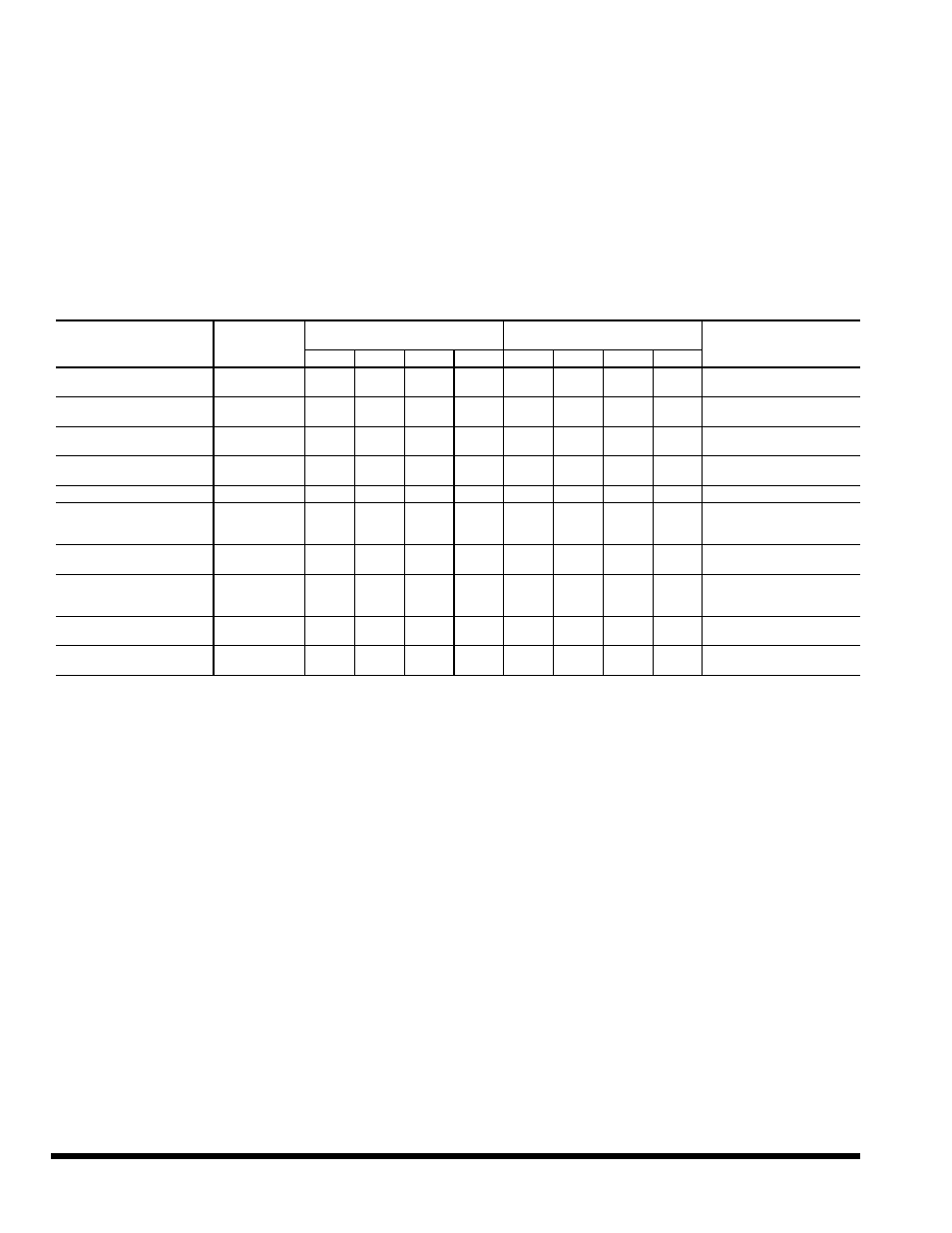
Table 13 — Troubleshooting
LEGEND
NOTE: Warning LEDs and error codes are found on the system con-
trol board.
FAULT DESCRIPTION
ERROR CODE
(COMMTSTAT)
SYSTEM WARNING (FLASH)
SYSTEM LOCKOUT (STEADY
ON)
POSSIBLE FAULT CAUSE
LED1
LED2
LED3
LED4
LED1
LED2
LED3
LED4
High Pressure Lockout
< 600 psi
Er 1
OFF
OFF
OFF
FLASH
OFF
OFF
OFF
ON
Low Airflow (Heating), Low
Water Flow (Cooling)
Low Pressure Lockout
< 40 psi
Er 2
OFF
OFF
FLASH
OFF
OFF
OFF
ON
OFF
Low Refrigerant Charge
Freeze Protection, Air
Side
Er 4
OFF
OFF
FLASH FLASH
OFF
OFF
ON
ON
Water Temperature < 35 F
or < 15 F (Heating)
Freeze Protection, Air
Side < 35 F
Er 5
OFF
FLASH
OFF
OFF
OFF
ON
OFF
OFF
Blower Failure (Cooling)
Condensate Overflow
Er 9, Er 10
OFF
FLASH
OFF
FLASH
OFF
ON
OFF
ON
Clogged Drain Line
Over/Under Low Voltage
Protection, 18-vac >
voltage, 30-vac
Er 11
OFF
FLASH FLASH
OFF
OFF
ON
ON
OFF
Loss of Power, Brown Out
LWT Sensor Failure (Low
Water Temperature)
Er 13
FLASH
OFF
OFF
OFF
N/A
N/A
N/A
N/A
Sensor Resistance Above
or Below Specification
DAT Sensor Failure
(Discharge Air
Temperature)
Er 14
FLASH
OFF
OFF
FLASH
N/A
N/A
N/A
N/A
Sensor Resistance Above
or Below Specification
FP1 Sensor Failure
(Freeze Protection)
Er 15
FLASH
OFF
FLASH
OFF
ON
OFF
ON
OFF
Sensor Resistance Above
or Below Specification
FP2 Sensor Failure
(Freeze Protection)
Er 16
FLASH
OFF
FLASH FLASH
ON
OFF
ON
ON
Sensor Resistance Above
or Below Specification
LED — Light-Emitting Diode