Carl Goldberg GBGA1045 User Manual
Page 6
6
2.
Attach the outboard servo to one side of the
Y-connector. Insert the Y-connector into the
outboard hole and guide down the wing to the
inboard servo hole. Pull the other side of the
y-connector through the hole and connect the
other servo. Continue pulling the y-connector
to the center of the wing.
Screw the two servos into place with the out-
put arms forward, using the hardware sup-
plied with the radio.
IMPO
RTANT! To ensure that any connections locat-
ed inside the wing will not come loose, either when
the wires are pulled, or during flying, always tape
them securely together with electrical tape.
3.
Tape the end of the plug to the root rib
.
Repeat for the other wing half.
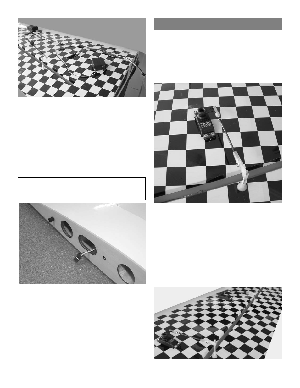
Aileron Servos Pushrods
1.
COLLECT THE FOLLOWING ITEMS:
(4) 4-40 X 3-1/8” PUSHRODS THREADED
BOTH ENDS
(4) 4-40 CLEVIS
(4) SILICONE CLEVIS RETAINERS
(4) 4-40 nuts
3.
Repeat for the other three servos
2.
Screw the 4-40 x 3-1/8” pushrod into the nylon
control horn fitting on the aileron.
Slide the silicone clevis retainer over the end
of the clevis.
Screw the nut then the clevis on the other end
of the pushrod.
Center the servo with the radio, make sure the
aileron is centered and adjust the clevis to fit
on the servo output arm.
After final adjustment, tighten nut against cle-
vis and put thread lock on nut.