Wing assembly – Carl Goldberg GBGA1045 User Manual
Page 4
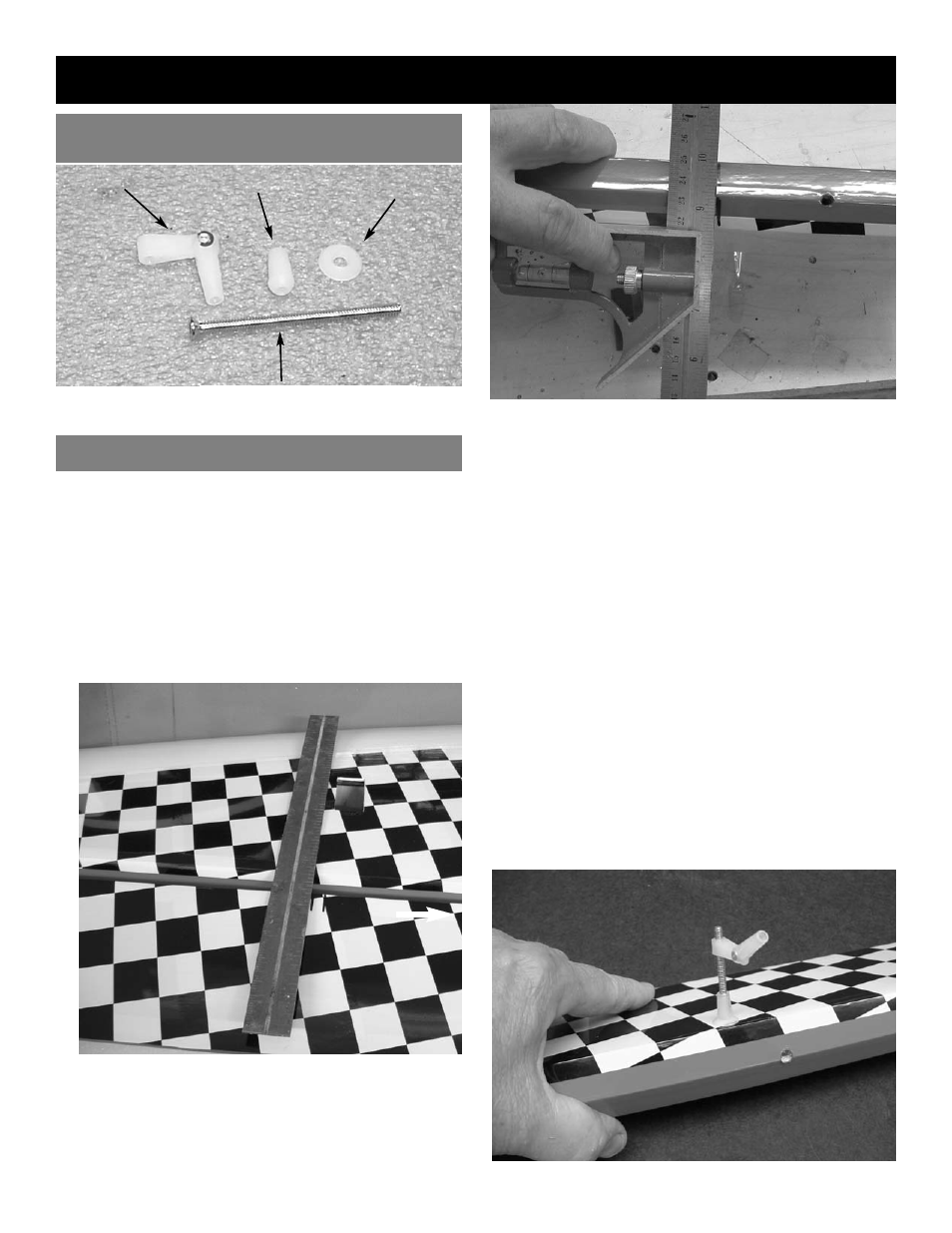
3.
Using a 1/8” drill, drill half way through the
aileron hole from both top and bottom till the
drill passes through the aileron.
Insert the 6-32 x 3” bolt into the top of the
aileron.
Thread the bolt all the way till the head is flush
with the top of the aileron.
4.
On the bottom of the aileron, place first the
cup washer then the nylon nut onto the 6-32
bolt.
Using a screwdriver tighten the nylon nut all
the way down till it rest in the cup washer and
is tight to the aileron.
Thread the nylon adjustable control horn onto
the bolt.(Note: Thread the side that you can
see the cut threads in the nylon onto the
bolt)
2.
With the aileron servo in place, make a mark
on the aileron at a 90º degree angle to the
trailing edge and in line with the servo. Look
for the control horn hard point under the cov-
ering. This is the location for the control horn.
4
AILERON CONTROL HORN INSTALLATION
1.
Collect the following items
(4) 4-40 x 3” socket head bolt
(4) Nylon Adjustable Control horns
(4) Nylon Nut
(4) Nylon Cup Washer
CONTROL HORN PART NAMES
WING ASSEMBLY
6-32 x 3” bolt
adjustable control
horn
nut
washer
Transfer the mark from the bottom of the
aileron to the top side.